ATmega64A
The synchronization and edge detector logic introduces a delay of 2.5 to 3.5 system clock cycles
from an edge has been applied to the Tn pin to the counter is updated.
Enabling and disabling of the clock input must be done when Tn has been stable for at least one
system clock cycle, otherwise it is a risk that a false Timer/Counter clock pulse is generated.
Each half period of the external clock applied must be longer than one system clock cycle to
ensure correct sampling. The external clock must be guaranteed to have less than half the sys-
tem clock frequency (fExtClk < fclk_I/O/2) given a 50/50% duty cycle. Since the edge detector uses
sampling, the maximum frequency of an external clock it can detect is half the sampling fre-
quency (Nyquist sampling theorem). However, due to variation of the system clock frequency
and duty cycle caused by Oscillator source (crystal, resonator, and capacitors) tolerances, it is
recommended that maximum frequency of an external clock source is less than fclk_I/O/2.5.
An external clock source can not be prescaled.
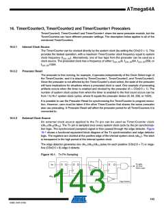
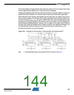
Figure 16-2. Prescaler for Timer/Counter1, Timer/Counter2, and Timer/Counter3(1)
CK
10-BIT T/C PRESCALER
Clear
PSR321
T3
T2
T1
0
0
0
CS30
CS31
CS32
CS20
CS21
CS22
CS10
CS11
CS12
TIMER/COUNTER3 CLOCK SOURCE
TIMER/COUNTER2 CLOCK SOURCE
TIMER/COUNTER1 CLOCK SOURCE
clkT3
clkT2
clkT1
Note:
1. The synchronization logic on the input pins (T3/T2/T1) is shown in Figure 16-1.
144
8160C–AVR–07/09

 ATMEL [ ATMEL ]