ATmega64A
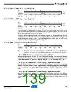
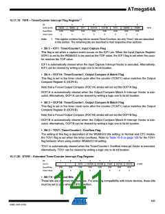
15.11.19 TIFR – Timer/Counter Interrupt Flag Register(1)
Bit
7
OCF2
R/W
0
6
TOV2
R/W
0
5
4
OCF1A
R/W
0
3
OCF1B
R/W
0
2
TOV1
R/W
0
1
0
0x36 (0x56)
Read/Write
Initial Value
ICF1
R/W
0
OCF0
R/W
0
TOV0
R/W
0
TIFR
Note:
1. This register contains flag bits for several Timer/Counters, but only Timer1 bits are described
in this section. The remaining bits are described in their respective timer sections.
• Bit 5 – ICF1: Timer/Counter1, Input Capture Flag
This flag is set when a capture event occurs on the ICP1 pin. When the Input Capture Register
(ICR1) is set by the WGMn3:0 to be used as the TOP value, the ICF1 flag is set when the coun-
ter reaches the TOP value.
ICF1 is automatically cleared when the Input Capture Interrupt Vector is executed. Alternatively,
ICF1 can be cleared by writing a logic one to its bit location.
• Bit 4 – OCF1A: Timer/Counter1, Output Compare A Match Flag
This flag is set in the timer clock cycle after the counter (TCNT1) value matches the Output
Compare Register A (OCR1A).
Note that a Forced Output Compare (FOC1A) strobe will not set the OCF1A flag.
OCF1A is automatically cleared when the Output Compare Match A Interrupt Vector is exe-
cuted. Alternatively, OCF1A can be cleared by writing a logic one to its bit location.
• Bit 3 – OCF1B: Timer/Counter1, Output Compare B Match Flag
This flag is set in the timer clock cycle after the counter (TCNT1) value matches the Output
Compare Register B (OCR1B).
Note that a Forced Output Compare (FOC1B) strobe will not set the OCF1B flag.
OCF1B is automatically cleared when the Output Compare Match B Interrupt Vector is exe-
cuted. Alternatively, OCF1B can be cleared by writing a logic one to its bit location.
• Bit 2 – TOV1: Timer/Counter1, Overflow Flag
The setting of this flag is dependent of the WGMn3:0 bits setting. In Normal and CTC modes,
the TOV1 flag is set when the timer overflows. Refer to Table 15-5 on page 135 for the TOV1
flag behavior when using another WGMn3:0 bit setting.
TOV1 is automatically cleared when the Timer/Counter1 Overflow Interrupt Vector is executed.
Alternatively, TOV1 can be cleared by writing a logic one to its bit location.
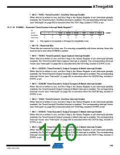
15.11.20 ETIFR – Extended Timer/Counter Interrupt Flag Register
Bit
(0x7C)
7
6
5
4
3
OCF3B
R/W
0
2
TOV3
R/W
0
1
OCF3C
R/W
0
0
OCF1C
R/W
0
–
–
ICF3
OCF3A
ETIFR
Read/Write
Initial Value
R/W
0
R/W
0
R/W
0
R/W
0
• Bit 7:6 – Reserved Bits
These bits are reserved for future use. For ensuring compatibility with future devices, these bits
must be set to zero when ETIFR is written.
141
8160C–AVR–07/09

 ATMEL [ ATMEL ]