is enabled on the corresponding I/O pin. If PCINT14..8 is cleared, pin change interrupt
on the corresponding I/O pin is disabled.
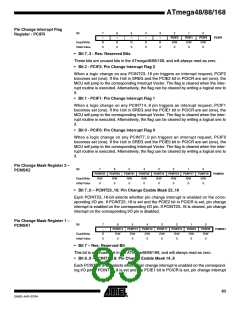
Pin Change Mask Register 0 –
PCMSK0
Bit
7
6
5
4
3
2
1
0
PCINT7
R/W
0
PCINT6
R/W
0
PCINT5
R/W
0
PCINT4
R/W
0
PCINT3
R/W
0
PCINT2
R/W
0
PCINT1
R/W
0
PCINT0
R/W
0
PCMSK0
Read/Write
Initial Value
• Bit 7..0 – PCINT7..0: Pin Change Enable Mask 7..0
Each PCINT7..0 bit selects whether pin change interrupt is enabled on the correspond-
ing I/O pin. If PCINT7..0 is set and the PCIE0 bit in PCICR is set, pin change interrupt is
enabled on the corresponding I/O pin. If PCINT7..0 is cleared, pin change interrupt on
the corresponding I/O pin is disabled.
84
ATmega48/88/168
2545D–AVR–07/04

 ATMEL [ ATMEL ]