ATmega48/88/168
The Timer/Counter2 can be clocked both synchronously and asynchronously in Power-
save mode. If Timer/Counter2 is not using the asynchronous clock, the Timer/Counter
Oscillator is stopped during sleep. If Timer/Counter2 is not using the synchronous clock,
the clock source is stopped during sleep. Note that even if the synchronous clock is run-
ning in Power-save, this clock is only available for Timer/Counter2.
Standby Mode
When the SM2..0 bits are 110 and an external crystal/resonator clock option is selected,
the SLEEP instruction makes the MCU enter Standby mode. This mode is identical to
Power-down with the exception that the Oscillator is kept running. From Standby mode,
the device wakes up in six clock cycles.
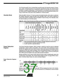
Table 19. Active Clock Domains and Wake-up Sources in the Different Sleep Modes.
Active Clock Domains Oscillators
Wake-up Sources
Sleep Mode
Idle
X
X
X
X
X
X
X
X(2)
X(2)
X
X
X
X
X
X
X
X
X
X
ADC Noise
Reduction
X(3)
X(3)
X(3)
X(3)
X
X
X
X
X
X
X
X
Power-down
Power-save
Standby(1)
X
X
X
X
Notes: 1. Only recommended with external crystal or resonator selected as clock source.
2. If Timer/Counter2 is running in asynchronous mode.
3. For INT1 and INT0, only level interrupt.
Power Reduction
Register
The Power Reduction Register, PRR, provides a method to stop the clock to individual
peripherals to reduce power consumption. The current state of the peripheral is frozen
and the I/O registers can not be read or written. Resources used by the peripheral when
stopping the clock will remain occupied, hence the peripheral should in most cases be
disabled before stopping the clock. Waking up a module, which is done by clearing the
bit in PRR, puts the module in the same state as before shutdown.
Module shutdown can be used in Idle mode and Active mode to significantly reduce the
overall power consumption. See “Power-Down Supply Current” on page 306 for exam-
ples. In all other sleep modes, the clock is already stopped.
Power Reduction Register -
PRR
Bit
7
PRTWI
R/W
0
6
PRTIM2
R/W
0
5
PRTIM0
R/W
0
4
–
3
PRTIM1
R/W
0
2
PRSPI
R/W
0
1
PRUSART0
R/W
0
PRADC
R/W
0
PRR
Read/Write
Initial Value
R
0
0
• Bit 7 - PRTWI: Power Reduction TWI
Writing a logic one to this bit shuts down the TWI by stopping the clock to the module.
When waking up the TWI again, the TWI should be re initialized to ensure proper
operation.
37
2545D–AVR–07/04

 ATMEL [ ATMEL ]