ATmega48/88/168
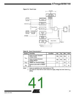
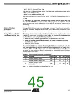
Figure 16. Reset Logic
DATA BUS
MCU Status
Register (MCUSR)
Power-on Reset
Circuit
Brown-out
Reset Circuit
BODLEVEL [2..0]
Pull-up Resistor
SPIKE
FILTER
RSTDISBL
Watchdog
Oscillator
Delay Counters
Clock
CK
Generator
TIMEOUT
CKSEL[3:0]
SUT[1:0]
Table 20. Reset Characteristics(1)
Symbol Parameter
Condition
Min
Typ
Max Units
Power-on Reset Threshold
Voltage (rising)
TBD TBD TBD
TBD TBD TBD
V
VPOT
Power-on Reset Threshold
V
V
Voltage (falling)(2)
VRST
tRST
RESET Pin Threshold Voltage
0.1
0.9
2.5
Minimum pulse width on RESET
Pin
µs
Notes: 1. Values are guidelines only. Actual values are TBD.
2. The Power-on Reset will not work unless the supply voltage has been below VPOT
(falling)
41
2545D–AVR–07/04

 ATMEL [ ATMEL ]