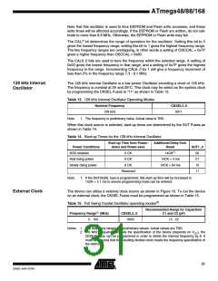
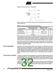
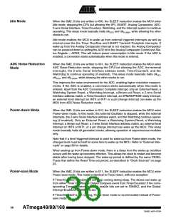
Figure 15. External Clock Drive Configuration
NC
XTAL2
EXTERNAL
CLOCK
XTAL1
GND
SIGNAL
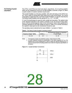
When this clock source is selected, start-up times are determined by the SUT Fuses as
shown in Table 16.
Table 16. Start-up Times for the External Clock Selection
Start-up Time from Power-
down and Power-save
Additional Delay from
Reset (VCC = 5.0V)
Power Conditions
BOD enabled
SUT1..0
00
6 CK
6 CK
14CK
Fast rising power
Slowly rising power
14CK + 4.1 ms
14CK + 65 ms
01
6 CK
10
Reserved
11
When applying an external clock, it is required to avoid sudden changes in the applied
clock frequency to ensure stable operation of the MCU. A variation in frequency of more
than 2ꢀ from one clock cycle to the next can lead to unpredictable behavior. If changes
of more than 2ꢀ is required, ensure that the MCU is kept in Reset during the changes.
Note that the System Clock Prescaler can be used to implement run-time changes of
the internal clock frequency while still ensuring stable operation. Refer to “System Clock
Prescaler” on page 33 for details.
Clock Output Buffer
The device can output the system clock on the CLKO pin. To enable the output, the
CKOUT Fuse has to be programmed. This mode is suitable when the chip clock is used
to drive other circuits on the system. The clock also will be output during reset, and the
normal operation of I/O pin will be overridden when the fuse is programmed. Any clock
source, including the internal RC Oscillator, can be selected when the clock is output on
CLKO. If the System Clock Prescaler is used, it is the divided system clock that is
output.
Timer/Counter Oscillator The device can operate its Timer/Counter2 from an external 32.768 kHz watch crystal or
a external clock source. The Timer/Counter Oscillator Pins (TOSC1 and TOSC2) are
shared with XTAL1 and XTAL2. This means that the Timer/Counter Oscillator can only
be used when an internal RC Oscillator is selected as system clock source. See Figure
13 on page 26 for crystal connection.
Applying an external clock source to TOSC1 requires EXTCLK in the ASSR Register
written to logic one. See “Asynchronous operation of the Timer/Counter” on page 149
for further description on selecting external clock as input instead of a 32 kHz crystal.
32
ATmega48/88/168
2545D–AVR–07/04

 ATMEL [ ATMEL ]