ATmega48/88/168
Note that this oscillator is used to time EEPROM and Flash write accesses, and these
write times will be affected accordingly. If the EEPROM or Flash are written, do not cali-
brate to more than 8.8 MHz. Otherwise, the EEPROM or Flash write may fail.
The CAL7 bit determines the range of operation for the oscillator. Setting this bit to 0
gives the lowest frequency range, setting this bit to 1 gives the highest frequency range.
The two frequency ranges are overlapping, in other words a setting of OSCCAL = 0x7F
gives a higher frequency than OSCCAL = 0x80.
The CAL6..0 bits are used to tune the frequency within the selected range. A setting of
0x00 gives the lowest frequency in that range, and a setting of 0x7F gives the highest
frequency in the range. Incrementing CAL6..0 by 1 will give a frequency increment of
less than 2ꢀ in the frequency range 7.3 - 8.1 MHz.
128 kHz Internal
Oscillator
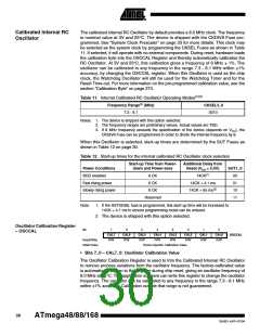
The 128 kHz internal Oscillator is a low power Oscillator providing a clock of 128 kHz.
The frequency is nominal at 3V and 25°C. This clock may be select as the system clock
by programming the CKSEL Fuses to “11” as shown in Table 13.
Table 13. 128 kHz Internal Oscillator Operating Modes
Nominal Frequency
CKSEL3..0
128 kHz
0011
Note:
1. The frequency is preliminary value. Actual value is TBD.
When this clock source is selected, start-up times are determined by the SUT Fuses as
shown in Table 14.
Table 14. Start-up Times for the 128 kHz Internal Oscillator
Start-up Time from Power-
down and Power-save
Additional Delay from
Reset
Power Conditions
BOD enabled
SUT1..0
00
6 CK
6 CK
14CK(1)
Fast rising power
Slowly rising power
14CK + 4 ms
14CK + 64 ms
01
6 CK
10
Reserved
11
Note:
1. If the RSTDISBL fuse is programmed, this start-up time will be increased to
14CK + 4.1 ms to ensure programming mode can be entered.
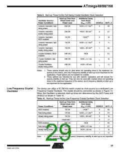
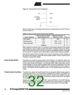
External Clock
The device can utilize a external clock source as shown in Figure 15. To run the device
on an external clock, the CKSEL Fuses must be programmed as shown in Table 15.
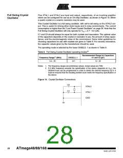
Table 15. Full Swing Crystal Oscillator operating modes(2)
Recommended Range for Capacitors
Frequency Range(1) (MHz)
CKSEL3..0
C1 and C2 (pF)
0 - 100
0000
12 - 22
Notes: 1. The frequency ranges are preliminary values. Actual values are TBD.
2. If 8 MHz frequency exceeds the specification of the device (depends on VCC), the
CKDIV8 Fuse can be programmed in order to divide the internal frequency by 8. It
must be ensured that the resulting divided clock meets the frequency specification of
the device.
31
2545D–AVR–07/04

 ATMEL [ ATMEL ]