Full Swing Crystal
Oscillator
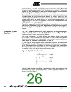
Pins XTAL1 and XTAL2 are input and output, respectively, of an inverting amplifier
which can be configured for use as an On-chip Oscillator, as shown in Figure 13. Either
a quartz crystal or a ceramic resonator may be used.
This Crystal Oscillator is a full swing oscillator, with rail-to-rail swing on the XTAL2 out-
put. This is useful for driving other clock inputs and in noisy environments. The current
consumption is higher than the “Low Power Crystal Oscillator” on page 26. Note that the
Full Swing Crystal Oscillator will only operate for VCC = 2.7 - 5.5 volts.
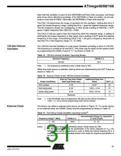
C1 and C2 should always be equal for both crystals and resonators. The optimal value
of the capacitors depends on the crystal or resonator in use, the amount of stray capac-
itance, and the electromagnetic noise of the environment. Some initial guidelines for
choosing capacitors for use with crystals are given in Table 9. For ceramic resonators,
the capacitor values given by the manufacturer should be used.
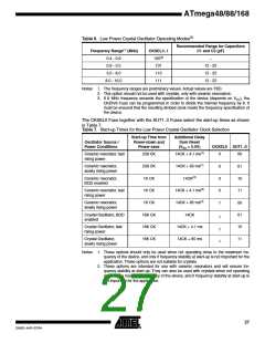
The operating mode is selected by the fuses CKSEL3..1 as shown in Table 8.
Table 8. Full Swing Crystal Oscillator operating modes(2)
Recommended Range for Capacitors
Frequency Range(1) (MHz)
CKSEL3..1
C1 and C2 (pF)
0.4 - 20
011
12 - 22
Notes: 1. The frequency ranges are preliminary values. Actual values are TBD.
2. If 8 MHz frequency exceeds the specification of the device (depends on VCC), the
CKDIV8 Fuse can be programmed in order to divide the internal frequency by 8. It
must be ensured that the resulting divided clock meets the frequency specification of
the device.
Figure 14. Crystal Oscillator Connections
C2
XTAL2
C1
XTAL1
GND
28
ATmega48/88/168
2545D–AVR–07/04

 ATMEL [ ATMEL ]