ATmega640/1280/1281/2560/2561
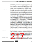
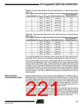
Table 99. Recommended Maximum Receiver Baud Rate Error for Normal Speed Mode
(U2Xn = 0)
D
Recommended Max
Receiver Error (%)
# (Data+Parity Bit)
R
slow (%)
93.20
94.12
94.81
95.36
95.81
96.17
Rfast (%)
106.67
105.79
105.11
104.58
104.14
103.78
Max Total Error (%)
+6.67/-6.8
5
6
3.0
2.5
2.0
2.0
1.5
1.5
+5.79/-5.88
+5.11/-5.19
+4.58/-4.54
+4.14/-4.19
+3.78/-3.83
7
8
9
10
Table 100. Recommended Maximum Receiver Baud Rate Error for Double Speed
Mode (U2Xn = 1)
D
Recommended Max
Receiver Error (%)
# (Data+Parity Bit) Rslow (%) Rfast (%) Max Total Error (%)
5
6
94.12
94.92
95.52
96.00
96.39
96.70
105.66
104.92
104,35
103.90
103.53
103.23
+5.66/-5.88
+4.92/-5.08
+4.35/-4.48
+3.90/-4.00
+3.53/-3.61
+3.23/-3.30
2.5
2.0
1.5
1.5
1.5
1.0
7
8
9
10
The recommendations of the maximum receiver baud rate error was made under the
assumption that the Receiver and Transmitter equally divides the maximum total error.
There are two possible sources for the receivers baud rate error. The Receiver’s system
clock (XTAL) will always have some minor instability over the supply voltage range and
the temperature range. When using a crystal to generate the system clock, this is rarely
a problem, but for a resonator the system clock may differ more than 2ꢀ depending of
the resonators tolerance. The second source for the error is more controllable. The baud
rate generator can not always do an exact division of the system frequency to get the
baud rate wanted. In this case an UBRR value that gives an acceptable low error can be
used if possible.
Multi-processor
Communication Mode
Setting the Multi-processor Communication mode (MPCMn) bit in UCSRnA enables a
filtering function of incoming frames received by the USART Receiver. Frames that do
not contain address information will be ignored and not put into the receive buffer. This
effectively reduces the number of incoming frames that has to be handled by the CPU,
in a system with multiple MCUs that communicate via the same serial bus. The Trans-
mitter is unaffected by the MPCMn setting, but has to be used differently when it is a
part of a system utilizing the Multi-processor Communication mode.
If the Receiver is set up to receive frames that contain 5 to 8 data bits, then the first stop
bit indicates if the frame contains data or address information. If the Receiver is set up
for frames with nine data bits, then the ninth bit (RXB8n) is used for identifying address
and data frames. When the frame type bit (the first stop or the ninth bit) is one, the frame
contains an address. When the frame type bit is zero the frame is a data frame.
221
2549A–AVR–03/05

 ATMEL [ ATMEL ]