ATmega8U2/16U2/32U2
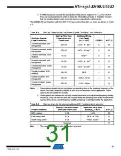
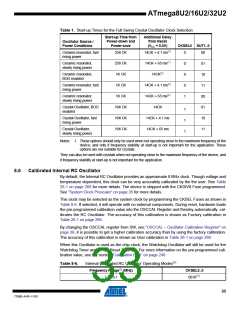
Table 1. Start-up Times for the Full Swing Crystal Oscillator Clock Selection
Start-up Time from
Power-down and
Power-save
Additional Delay
from Reset
Oscillator Source /
Power Conditions
(VCC = 5.0V)
CKSEL0 SUT1..0
Ceramic resonator, fast
rising power
258 CK
258 CK
1K CK
14CK + 4.1 ms(1)
14CK + 65 ms(1)
14CK(2)
0
0
0
0
1
00
01
10
11
00
01
10
11
Ceramic resonator,
slowly rising power
Ceramic resonator,
BOD enabled
Ceramic resonator, fast
rising power
1K CK
14CK + 4.1 ms(2)
14CK + 65 ms(2)
14CK
Ceramic resonator,
slowly rising power
1K CK
Crystal Oscillator, BOD
enabled
16K CK
16K CK
16K CK
1
1
1
Crystal Oscillator, fast
rising power
14CK + 4.1 ms
14CK + 65 ms
Crystal Oscillator,
slowly rising power
Notes: 1. These options should only be used when not operating close to the maximum frequency of the
device, and only if frequency stability at start-up is not important for the application. These
options are not suitable for crystals.
They can also be used with crystals when not operating close to the maximum frequency of the device, and
if frequency stability at start-up is not important for the application.
8.6
Calibrated Internal RC Oscillator
By default, the Internal RC Oscillator provides an approximate 8 MHz clock. Though voltage and
temperature dependent, this clock can be very accurately calibrated by the the user. See Table
26-1 on page 266 for more details. The device is shipped with the CKDIV8 Fuse programmed.
See “System Clock Prescaler” on page 35 for more details.
This clock may be selected as the system clock by programming the CKSEL Fuses as shown in
Table 8-6. If selected, it will operate with no external components. During reset, hardware loads
the pre-programmed calibration value into the OSCCAL Register and thereby automatically cal-
ibrates the RC Oscillator. The accuracy of this calibration is shown as Factory calibration in
Table 26-1 on page 266.
By changing the OSCCAL register from SW, see “OSCCAL – Oscillator Calibration Register” on
page 38, it is possible to get a higher calibration accuracy than by using the factory calibration.
The accuracy of this calibration is shown as User calibration in Table 26-1 on page 266.
When this Oscillator is used as the chip clock, the Watchdog Oscillator will still be used for the
Watchdog Timer and for the Reset Time-out. For more information on the pre-programmed cali-
bration value, see the section “Calibration Byte” on page 249.
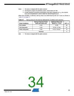
Table 8-6.
Internal Calibrated RC Oscillator Operating Modes(3)
Frequency Range(2) (MHz)
CKSEL3..0
7.3 - 8.1
0010(1)
33
7799D–AVR–11/10

 ATMEL [ ATMEL ]