ATmega8U2/16U2/32U2
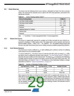
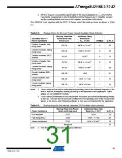
The oscillator is required to oscillate for a minimum number of cycles before the clock is consid-
ered stable. An internal ripple counter monitors the oscillator output clock, and keeps the internal
reset active for a given number of clock cycles. The reset is then released and the device will
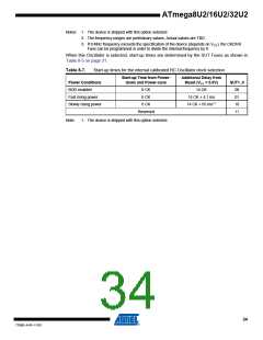
start to execute. The recommended oscillator start-up time is dependent on the clock type, and
varies from 6 cycles for an externally applied clock to 32K cycles for a low frequency crystal.
The start-up sequence for the clock includes both the time-out delay and the start-up time when
the device starts up from reset. When starting up from Power-save or Power-down mode, Vcc is
assumed to be at a sufficient level and only the start-up time is included.
8.4
Low Power Crystal Oscillator
Pins XTAL1 and XTAL2 are input and output, respectively, of an inverting amplifier which can be
configured for use as an On-chip Oscillator, as shown in Figure 8-4. Either a quartz crystal or a
ceramic resonator may be used.
This Crystal Oscillator is a low power oscillator, with reduced voltage swing on the XTAL2 out-
put. It gives the lowest power consumption, but is not capable of driving other clock inputs, and
may be more susceptible to noise in noisy environments.
C1 and C2 should always be equal for both crystals and resonators. The optimal value of the
capacitors depends on the crystal or resonator in use, the amount of stray capacitance, and the
electromagnetic noise of the environment. Some initial guidelines for choosing capacitors for
use with crystals are given in Table 8-3. For ceramic resonators, the capacitor values given by
the manufacturer should be used.
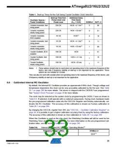
Figure 8-4. Crystal Oscillator Connections
C2
XTAL2
C1
XTAL1
GND
The Low Power Oscillator can operate in three different modes, each optimized for a specific fre-
quency range. The operating mode is selected by the fuses CKSEL3..1 as shown in Table 8-3.
Table 8-3.
Low Power Crystal Oscillator Operating Modes(3)
Recommended Range for Capacitors C1
Frequency Range(1) (MHz)
CKSEL3..1
100(2)
101
and C2 (pF)
0.4 - 0.9
0.9 - 3.0
3.0 - 8.0
8.0 - 16.0
–
12 - 22
12 - 22
12 - 22
110
111
Notes: 1. The frequency ranges are preliminary values. Actual values are TBD.
2. This option should not be used with crystals, only with ceramic resonators.
30
7799D–AVR–11/10

 ATMEL [ ATMEL ]