ATmega8U2/16U2/32U2
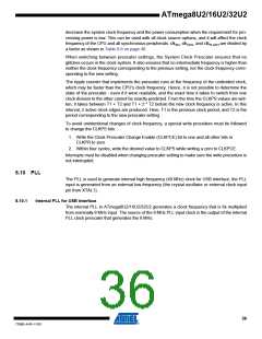
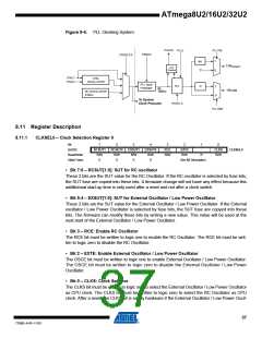
Figure 8-6. PLL Clocking System
PLOCK
PLLE
PLLITM
PINDIV
CKSEL3:0
/48
T1
1
0
Tclk
Timer1
Lock
Detector
XTAL1
XTAL2
XTAL
OSCILLATOR
PLL clock
Prescaler
PLL
/2
1
0
clk
8MHz
clk
USB
RC OSCILLATOR
8 MHz
To System
Clock Prescaler
PDIV3..0
PLLUSB
8.11 Register Description
8.11.1
CLKSEL0 – Clock Selection Register 0
Bit
7
RCSUT1
R/W
6
RCSUT0
R/W
5
4
3
2
1
0
(0xD0)
EXSUT1
R/W
0
EXSUT0
R/W
0
RCE
R/W
EXTE
-
CLKS
R/W
CLKSEL0
Read/Write
Initial Value
R/W
R
0
0
See Bit Description
• Bit 7:6 – RCSUT[1:0]: SUT for RC oscillator
These 2 bits are the SUT value for the RC Oscillator. If the RC oscillator is selected by fuse bits,
the SUT fuse are copied into these bits. A firmware change will not have any effect because this
additionnal start-up time is only used after a reset and not after a clock switch.
• Bit 5:4 – EXSUT[1:0]: SUT for External Oscillator / Low Power Oscillator
These 2 bits are the SUT value for the External Oscillator / Low Power Oscillator. If the External
oscillator / Low Power Oscillator is selected by fuse bits, the SUT fuse are copyed into these
bits. The firmware can modify these bits by writing a new value. This value will be used at the
next start of the External Oscillator / Low Power Oscillator.
• Bit 3 – RCE: Enable RC Oscillator
The RCE bit must be written to logic one to enable the RC Oscillator. The RCE bit must be writ-
ten to logic zero to disable the RC Oscillator.
• Bit 2 – EXTE: Enable External Oscillator / Low Power Oscillator
The OSCE bit must be written to logic one to enable External Oscillator / Low Power Oscillator.
The OSCE bit must be written to logic zero to disable the External Oscillator / Low Power
Oscillator.
• Bit 0 – CLKS: Clock Selector
The CLKS bit must be written to logic one to select the External Oscillator / Low Power Oscillator
as CPU clock. The CLKS bit must be written to logic zero to select the RC Oscillator as CPU
clock. After a reset, the CLKS bit is set by hardware if the External Oscillator / Low Power Oscil-
37
7799D–AVR–11/10

 ATMEL [ ATMEL ]