ATmega8U2/16U2/32U2
3. If 8 MHz frequency exceeds the specification of the device (depends on VCC), the CKDIV8
Fuse can be programmed in order to divide the internal frequency by 8. It must be ensured
that the resulting divided clock meets the frequency specification of the device.
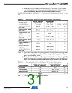
The CKSEL0 Fuse together with the SUT1..0 Fuses select the start-up times as shown in Table
8-4.
Table 8-4.
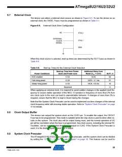
Start-up Times for the Low Power Crystal Oscillator Clock Selection
Start-up Time from
Power-down and
Power-save
Additional Delay
from Reset
Oscillator Source /
Power Conditions
(VCC = 5.0V)
CKSEL0
SUT1..0
Ceramic resonator, fast
rising power
258 CK
258 CK
1K CK
14CK + 4.1 ms(1)
14CK + 65 ms(1)
14CK(2)
0
00
Ceramic resonator, slowly
rising power
0
0
0
1
1
1
1
01
10
11
00
01
10
11
Ceramic resonator, BOD
enabled
Ceramic resonator, fast
rising power
1K CK
14CK + 4.1 ms(2)
14CK + 65 ms(2)
14CK
Ceramic resonator, slowly
rising power
1K CK
Crystal Oscillator, BOD
enabled
16K CK
16K CK
16K CK
Crystal Oscillator, fast
rising power
14CK + 4.1 ms
14CK + 65 ms
Crystal Oscillator, slowly
rising power
Notes: 1. These options should only be used when not operating close to the maximum frequency of the
device, and only if frequency stability at start-up is not important for the application. These
options are not suitable for crystals.
2. These options are intended for use with ceramic resonators and will ensure frequency stability
at start-up. They can also be used with crystals when not operating close to the maximum fre-
quency of the device, and if frequency stability at start-up is not important for the application.
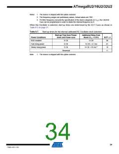
Table 8-5.
Start-up times for the internal calibrated RC Oscillator clock selection
Start-up Time from Power-
down and Power-save
Additional Delay from
Reset (VCC = 5.0V)
Power Conditions
BOD enabled
SUT1..0
00
6 CK
6 CK
14CK
Fast rising power
Slowly rising power
14CK + 4.1 ms
14CK + 65 ms(1)
01
6 CK
10
Reserved
11
Note:
1. The device is shipped with this option selected.
31
7799D–AVR–11/10

 ATMEL [ ATMEL ]