ATmega8U2/16U2/32U2
decrease the system clock frequency and the power consumption when the requirement for pro-
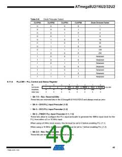
cessing power is low. This can be used with all clock source options, and it will affect the clock
frequency of the CPU and all synchronous peripherals. clkI/O, clkCPU, and clkFLASH are divided by
a factor as shown in Table 8-9 on page 40.
When switching between prescaler settings, the System Clock Prescaler ensures that no
glitches occurs in the clock system. It also ensures that no intermediate frequency is higher than
neither the clock frequency corresponding to the previous setting, nor the clock frequency corre-
sponding to the new setting.
The ripple counter that implements the prescaler runs at the frequency of the undivided clock,
which may be faster than the CPU's clock frequency. Hence, it is not possible to determine the
state of the prescaler - even if it were readable, and the exact time it takes to switch from one
clock division to the other cannot be exactly predicted. From the time the CLKPS values are writ-
ten, it takes between T1 + T2 and T1 + 2 * T2 before the new clock frequency is active. In this
interval, 2 active clock edges are produced. Here, T1 is the previous clock period, and T2 is the
period corresponding to the new prescaler setting.
To avoid unintentional changes of clock frequency, a special write procedure must be followed
to change the CLKPS bits:
1. Write the Clock Prescaler Change Enable (CLKPCE) bit to one and all other bits in
CLKPR to zero.
2. Within four cycles, write the desired value to CLKPS while writing a zero to CLKPCE.
Interrupts must be disabled when changing prescaler setting to make sure the write procedure is
not interrupted.
8.10 PLL
The PLL is used to generate internal high frequency (48 MHz) clock for USB interface, the PLL
input is generated from an external low-frequency (the crystal oscillator or external clock input
pin from XTAL1).
8.10.1
Internal PLL for USB interface
The internal PLL in ATmega8U2/16U2/32U2 generates a clock frequency that is 6x multiplied
from nominally 8 MHz input. The source of the 8 MHz PLL input clock is the output of the internal
PLL clock prescaler that generates the 8 MHz.
36
7799D–AVR–11/10

 ATMEL [ ATMEL ]