22.5 LCD Register Description
22.5.1
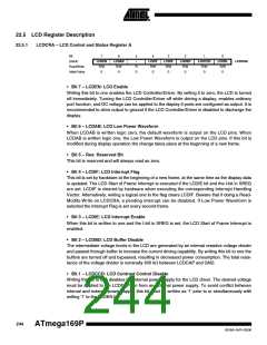
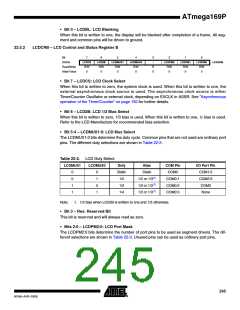
LCDCRA – LCD Control and Status Register A
Bit
7
LCDEN
R/W
0
6
LCDAB
R/W
0
5
–
4
LCDIF
R/W
0
3
LCDIE
R/W
0
2
LCDBD
R/W
0
1
LCDCCD
R/W
0
LCDBL
R/W
0
(0xE4)
LCDCRA
Read/Write
Initial Value
R
0
0
• Bit 7 – LCDEN: LCD Enable
Writing this bit to one enables the LCD Controller/Driver. By writing it to zero, the LCD is turned
off immediately. Turning the LCD Controller/Driver off while driving a display, enables ordinary
port function, and DC voltage can be applied to the display if ports are configured as output. It is
recommended to drive output to ground if the LCD Controller/Driver is disabled to discharge the
display.
• Bit 6 – LCDAB: LCD Low Power Waveform
When LCDAB is written logic zero, the default waveform is output on the LCD pins. When
LCDAB is written logic one, the Low Power Waveform is output on the LCD pins. If this bit is
modified during display operation the change takes place at the beginning of a new frame.
• Bit 5 – Res: Reserved Bit
This bit is reserved and will always read as zero.
• Bit 4 – LCDIF: LCD Interrupt Flag
This bit is set by hardware at the beginning of a new frame, at the same time as the display data
is updated. The LCD Start of Frame Interrupt is executed if the LCDIE bit and the I-bit in SREG
are set. LCDIF is cleared by hardware when executing the corresponding Interrupt Handling
Vector. Alternatively, writing a logical one to the flag clears LCDIF. Beware that if doing a Read-
Modify-Write on LCDCRA, a pending interrupt can be disabled. If Low Power Waveform is
selected the Interrupt Flag is set every second frame.
• Bit 3 – LCDIE: LCD Interrupt Enable
When this bit is written to one and the I-bit in SREG is set, the LCD Start of Frame Interrupt is
enabled.
• Bit 2 – LCDBD: LCD Buffer Disable
The intermediate voltage levels in the LCD are generated by an internal resistive voltage divider
and passed through buffer to increase the current driving capability. By writing this bit to one the
buffers are turned off and bypassed, resulting in decreased power consumption. The total resis-
tance of the voltage divider is nominally 400 kΩ between LCDCAP and GND.
• Bit 1 – LCDCCD: LCD Contrast Control Disable
Writing this bit to one disables the internal power supply for the LCD driver. The desired voltage
must be applied to the LCDCAP pin from an external power supply. To avoid conflict between
internal and external power supply, this bit must be written as '1' prior to or simultaneously with
writing '1' to the LCDEN bit.
244
ATmega169P
8018A–AVR–03/06

 ATMEL [ ATMEL ]