ATmega169P
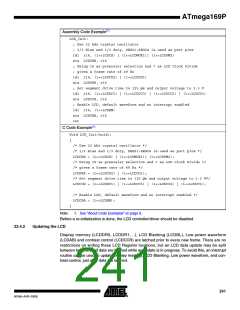
Assembly Code Example(1)
LCD_Init:
; Use 32 kHz crystal oscillator
; 1/3 Bias and 1/3 duty, SEG21:SEG24 is used as port pins
ldi r16, (1<<LCDCS) | (1<<LCDMUX1)| (1<<LCDPM2)
sts LCDCRB, r16
; Using 16 as prescaler selection and 7 as LCD Clock Divide
; gives a frame rate of 49 Hz
ldi r16, (1<<LCDCD2) | (1<<LCDCD1)
sts LCDFRR, r16
; Set segment drive time to 125 µs and output voltage to 3.3 V
ldi r16, (1<<LCDDC1) | (1<<LCDCC3) | (1<<LCDCC2) | (1<<LCDCC1)
sts LCDCCR, r16
; Enable LCD, default waveform and no interrupt enabled
ldi r16, (1<<LCDEN)
sts LCDCRA, r16
ret
C Code Example(1)
Void LCD_Init(void);
{
/* Use 32 kHz crystal oscillator */
/* 1/3 Bias and 1/3 duty, SEG21:SEG24 is used as port pins */
LCDCRB = (1<<LCDCS) | (1<<LCDMUX1)| (1<<LCDPM2);
/* Using 16 as prescaler selection and 7 as LCD Clock Divide */
/* gives a frame rate of 49 Hz */
LCDFRR = (1<<LCDCD2) | (1<<LCDCD1);
/* Set segment drive time to 125 µs and output voltage to 3.3 V*/
LCDCCR = (1<<LCDDC1) | (1<<LCDCC3) | (1<<LCDCC2) | (1<<LCDCC1);
/* Enable LCD, default waveform and no interrupt enabled */
LCDCRA = (1<<LCDEN);
}
Note:
1. See ”About Code Examples” on page 9.
Before a re-initialization is done, the LCD controller/driver should be disabled
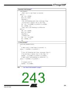
Updating the LCD
22.4.2
Display memory (LCDDR0, LCDDR1, ..), LCD Blanking (LCDBL), Low power waveform
(LCDAB) and contrast control (LCDCCR) are latched prior to every new frame. There are no
restrictions on writing these LCD Register locations, but an LCD data update may be split
between two frames if data are latched while an update is in progress. To avoid this, an interrupt
routine can be used to update Display memory, LCD Blanking, Low power waveform, and con-
trast control, just after data are latched.
241
8018A–AVR–03/06

 ATMEL [ ATMEL ]