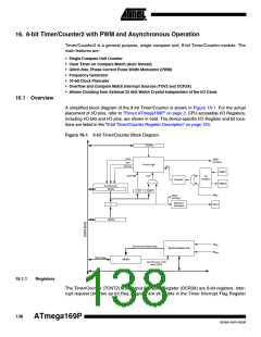
16. 8-bit Timer/Counter2 with PWM and Asynchronous Operation
Timer/Counter2 is a general purpose, single compare unit, 8-bit Timer/Counter module. The
main features are:
• Single Compare Unit Counter
• Clear Timer on Compare Match (Auto Reload)
• Glitch-free, Phase Correct Pulse Width Modulator (PWM)
• Frequency Generator
• 10-bit Clock Prescaler
• Overflow and Compare Match Interrupt Sources (TOV2 and OCF2A)
• Allows Clocking from External 32 kHz Watch Crystal Independent of the I/O Clock
16.1 Overview
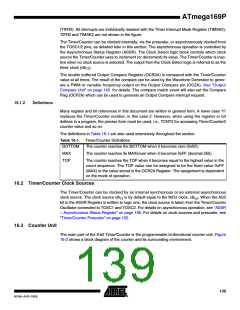
A simplified block diagram of the 8-bit Timer/Counter is shown in Figure 16-1. For the actual
placement of I/O pins, refer to ”Pinout ATmega169P” on page 2. CPU accessible I/O Registers,
including I/O bits and I/O pins, are shown in bold. The device-specific I/O Register and bit loca-
tions are listed in the ”8-bit Timer/Counter Register Description” on page 153.
Figure 16-1. 8-bit Timer/Counter Block Diagram
TCCRnx
count
TOVn
(Int.Req.)
clear
Control Logic
TOP
direction
clkTn
TOSC1
BOTTOM
T/C
Oscillator
Prescaler
TOSC2
Timer/Counter
TCNTn
= 0
= 0xFF
clkI/O
OCnx
(Int.Req.)
Waveform
Generation
OCnx
=
OCRnx
clkI/O
Synchronized Status flags
Synchronization Unit
clkASY
Status flags
ASSRn
asynchronous mode
select (ASn)
16.1.1
Registers
The Timer/Counter (TCNT2) and Output Compare Register (OCR2A) are 8-bit registers. Inter-
rupt request (shorten as Int.Req.) signals are all visible in the Timer Interrupt Flag Register
138
ATmega169P
8018A–AVR–03/06

 ATMEL [ ATMEL ]