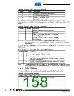
Table 65. Compare Output Mode, Non-PWM Mode
COM21
COM20
Description
0
0
1
1
0
1
0
1
Normal port operation, OC2 disconnected.
Toggle OC2 on compare match
Clear OC2 on compare match
Set OC2 on compare match
Table 66 shows the COM21:0 bit functionality when the WGM21:0 bits are set to fast PWM
mode.
Table 66. Compare Output Mode, Fast PWM Mode(1)
COM21
COM20
Description
0
0
1
0
1
0
Normal port operation, OC2 disconnected.
Reserved
Clear OC2 on compare match, set OC2 at BOTTOM,
(non-inverting mode)
1
1
Set OC2 on compare match, clear OC2 at BOTTOM,
(inverting mode)
Note:
1. A special case occurs when OCR2 equals TOP and COM21 is set. In this case, the compare
match is ignored, but the set or clear is done at BOTTOM. See “Fast PWM Mode” on page 151
for more details.
Table 67 shows the COM21:0 bit functionality when the WGM21:0 bits are set to phase correct
PWM mode.
Table 67. Compare Output Mode, Phase Correct PWM Mode(1)
COM21 COM20 Description
0
0
1
0
1
0
Normal port operation, OC2 disconnected.
Reserved
Clear OC2 on compare match when up-counting. Set OC2 on compare
match when downcounting.
1
1
Set OC2 on compare match when up-counting. Clear OC2 on compare
match when downcounting.
Note:
1. A special case occurs when OCR2 equals TOP and COM21 is set. In this case, the compare
match is ignored, but the set or clear is done at TOP. See “Phase Correct PWM Mode” on page
153 for more details.
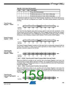
• Bit 2:0 – CS22:0: Clock Select
The three clock select bits select the clock source to be used by the Timer/Counter.
Table 68. Clock Select Bit Description
CS22
CS21
CS20
Description
0
0
0
0
1
0
0
1
1
0
0
1
0
1
0
No clock source (Timer/Counter stopped)
clkI/O/(No prescaling)
clkI/O/8 (From prescaler)
clkI/O/64 (From prescaler)
clkI/O/256 (From prescaler)
158
ATmega128(L)
2467P–AVR–08/07

 ATMEL [ ATMEL ]