10.2.2
I/O Clock – clkI/O
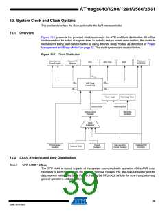
The I/O clock is used by the majority of the I/O modules, like Timer/Counters, SPI, and USART.
The I/O clock is also used by the External Interrupt module, but note that some external inter-
rupts are detected by asynchronous logic, allowing such interrupts to be detected even if the I/O
clock is halted. Also note that start condition detection in the USI module is carried out asynchro-
nously when clkI/O is halted, TWI address recognition in all sleep modes.
10.2.3
10.2.4
Flash Clock – clkFLASH
The Flash clock controls operation of the Flash interface. The Flash clock is usually active simul-
taneously with the CPU clock.
Asynchronous Timer Clock – clkASY
The Asynchronous Timer clock allows the Asynchronous Timer/Counter to be clocked directly
from an external clock or an external 32 kHz clock crystal. The dedicated clock domain allows
using this Timer/Counter as a real-time counter even when the device is in sleep mode.
10.2.5
ADC Clock – clkADC
The ADC is provided with a dedicated clock domain. This allows halting the CPU and I/O clocks
in order to reduce noise generated by digital circuitry. This gives more accurate ADC conversion
results.
10.3 Clock Sources
The device has the following clock source options, selectable by Flash Fuse bits as shown
below. The clock from the selected source is input to the AVR clock generator, and routed to the
appropriate modules.
Table 10-1. Device Clocking Options Select(1)
Device Clocking Option
Low Power Crystal Oscillator
Full Swing Crystal Oscillator
Low Frequency Crystal Oscillator
Internal 128 kHz RC Oscillator
Calibrated Internal RC Oscillator
External Clock
CKSEL3:0
1111 - 1000
0111 - 0110
0101 - 0100
0011
0010
0000
Reserved
0001
Note:
1. For all fuses “1” means unprogrammed while “0” means programmed.
40
ATmega640/1280/1281/2560/2561
2549L–AVR–08/07

 ATMEL [ ATMEL ]