C1 and C2 should always be equal for both crystals and resonators. The optimal value of the
capacitors depends on the crystal or resonator in use, the amount of stray capacitance, and the
electromagnetic noise of the environment. Some initial guidelines for choosing capacitors for
use with crystals are given in Table 10-3. For ceramic resonators, the capacitor values given by
the manufacturer should be used.
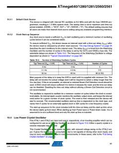
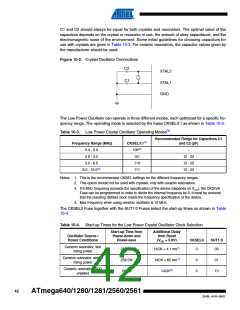
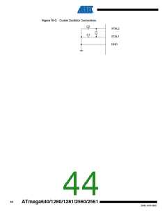
Figure 10-2. Crystal Oscillator Connections
C2
XTAL2
C1
XTAL1
GND
The Low Power Oscillator can operate in three different modes, each optimized for a specific fre-
quency range. The operating mode is selected by the fuses CKSEL3:1 as shown in Table 10-3.
Table 10-3. Low Power Crystal Oscillator Operating Modes(3)
Recommended Range for Capacitors C1
Frequency Range (MHz)
0.4 - 0.9
CKSEL3:1(1)
100(2)
101
and C2 (pF)
–
0.9 - 3.0
12 - 22
12 - 22
12 - 22
3.0 - 8.0
110
8.0 - 16.0(4)
111
Notes: 1. This is the recommended CKSEL settings for the different frequency ranges.
2. This option should not be used with crystals, only with ceramic resonators.
3. If 8 MHz frequency exceeds the specification of the device (depends on VCC), the CKDIV8
Fuse can be programmed in order to divide the internal frequency by 8. It must be ensured
that the resulting divided clock meets the frequency specification of the device.
4. Max frequency when using ceramic oscillator is 10 MHz.
The CKSEL0 Fuse together with the SUT1:0 Fuses select the start-up times as shown in Table
10-4.
Table 10-4. Start-up Times for the Low Power Crystal Oscillator Clock Selection
Start-up Time from
Power-down and
Power-save
Additional Delay
from Reset
Oscillator Source /
Power Conditions
(VCC = 5.0V)
CKSEL0
SUT1:0
Ceramic resonator, fast
rising power
258 CK
258 CK
1K CK
14CK + 4.1 ms(1)
14CK + 65 ms(1)
14CK(2)
0
00
Ceramic resonator, slowly
rising power
0
0
01
10
Ceramic resonator, BOD
enabled
42
ATmega640/1280/1281/2560/2561
2549L–AVR–08/07

 ATMEL [ ATMEL ]