ATmega640/1280/1281/2560/2561
10. System Clock and Clock Options
This section describes the clock options for the AVR microcontroller.
10.1 Overview
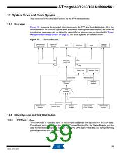
Figure 10-1 presents the principal clock systems in the AVR and their distribution. All of the
clocks need not be active at a given time. In order to reduce power consumption, the clocks to
modules not being used can be halted by using different sleep modes, as described in “Power
Management and Sleep Modes” on page 52. The clock systems are detailed below.
Figure 10-1. Clock Distribution
Asynchronous
Timer/Counter
General I/O
Modules
Flash and
EEPROM
ADC
CPU Core
RAM
clkADC
clkI/O
clkCPU
AVR Clock
Control Unit
clkASY
clkFLASH
Reset Logic
Watchdog Timer
Source clock
Watchdog clock
Watchdog
Oscillator
System Clock
Prescaler
Clock
Multiplexer
Timer/Counter
Oscillator
Crystal
Oscillator
Low-frequency
Crystal Oscillator
Calibrated RC
Oscillator
External Clock
10.2 Clock Systems and their Distribution
10.2.1
CPU Clock – clkCPU
The CPU clock is routed to parts of the system concerned with operation of the AVR core.
Examples of such modules are the General Purpose Register File, the Status Register and the
data memory holding the Stack Pointer. Halting the CPU clock inhibits the core from performing
general operations and calculations.
39
2549L–AVR–08/07

 ATMEL [ ATMEL ]