ATmega640/1280/1281/2560/2561
of the Interrupt Flag. The Output Compare pin is changed on the timer clock and is not
synchronized to the processor clock.
20.9 Timer/Counter Prescaler
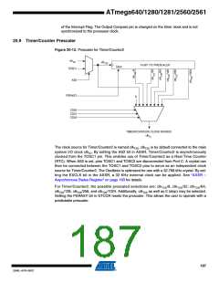
Figure 20-12. Prescaler for Timer/Counter2
clkI/O
clkT2S
10-BIT T/C PRESCALER
Clear
TOSC1
AS2
PSRASY
0
CS20
CS21
CS22
TIMER/COUNTER2 CLOCK SOURCE
clkT2
The clock source for Timer/Counter2 is named clkT2S. clkT2S is by default connected to the main
system I/O clock clkIO. By setting the AS2 bit in ASSR, Timer/Counter2 is asynchronously
clocked from the TOSC1 pin. This enables use of Timer/Counter2 as a Real Time Counter
(RTC). When AS2 is set, pins TOSC1 and TOSC2 are disconnected from Port C. A crystal can
then be connected between the TOSC1 and TOSC2 pins to serve as an independent clock
source for Timer/Counter2. The Oscillator is optimized for use with a 32.768 kHz crystal. By set-
ting the EXCLK bit in the ASSR, a 32 KHz external clock can be applied. See “ASSR –
Asynchronous Status Register” on page 193 for details.
For Timer/Counter2, the possible prescaled selections are: clkT2S/8, clkT2S/32, clkT2S/64,
clkT2S/128, clkT2S/256, and clkT2S/1024. Additionally, clkT2S as well as 0 (stop) may be selected.
Setting the PSRASY bit in GTCCR resets the prescaler. This allows the user to operate with a
predictable prescaler.
187
2549L–AVR–08/07

 ATMEL [ ATMEL ]