This bit is available for both USART and EUSART mode.
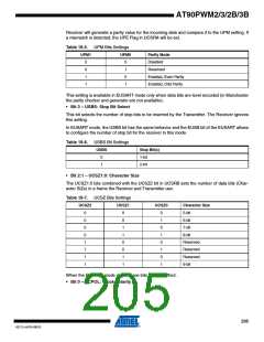
• Bit 2 – UCSZ2: Character Size
The UCSZ2 bits combined with the UCSZ1:0 bit in UCSRC sets the number of data bits (Char-
acter SiZe) in a frame the Receiver and Transmitter use.
This bit have no effect when the EUSART mode is enabled.
• Bit 1 – RXB8: Receive Data Bit 8
RXB8 is the ninth data bit of the received character when operating with serial frames with nine
data bits. Must be read before reading the low bits from UDR.
When the EUSART mode is enable and configured in 17 bits receive mode, this bit contains the
seventeenth bit (see EUSART section).
• Bit 0 – TXB8: Transmit Data Bit 8
TXB8 is the ninth data bit in the character to be transmitted when operating with serial frames
with nine data bits. Must be written before writing the low bits to UDR.
When the EUSART mode is enable and configured in 17 bits transmit mode, this bit contains the
seventeenth bit (See EUSART section).
18.10.4 USART Control and Status Register C – UCSRC
Bit
7
6
5
4
UPM0
R/W
0
3
USBS
R/W
0
2
UCSZ1
R/W
1
1
UCSZ0
R/W
1
0
UCPOL
R/W
0
-
UMSEL0
UPM1
R/W
0
UCSRC
Read/Write
Initial Value
R/W
0
R/W
0
• Bit 7 – Reserved Bit
This bit is reserved for future use. For compatibilty with future devices, this bit must be written to
zero when USCRC is written.
• Bit 6 – UMSEL: USART Mode Select
This bit selects between asynchronous and synchronous mode of operation.
Table 18-4. UMSEL Bit Settings
UMSEL
Mode
0
1
Asynchronous Operation
Synchronous Operation
When configured in EUSART mode, the synchronous mode should not be set with Manchester
mode (See EUSART section).
• Bit 5:4 – UPM1:0: Parity Mode
These bits enable and set type of parity generation and check. If enabled, the Transmitter will
automatically generate and send the parity of the transmitted data bits within each frame. The
204
AT90PWM2/3/2B/3B
4317J–AVR–08/10

 ATMEL [ ATMEL ]