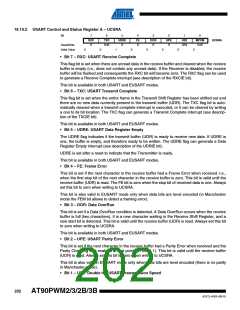
18.10.2 USART Control and Status Register A – UCSRA
Bit
7
RXC
R
6
5
UDRE
R
4
FE
R
3
DOR
R
2
UPE
R
1
0
TXC
R/W
U2X
R/W
MPCM
R/W
UCSRA
Read/Write
Initial Value
0
0
1
0
0
0
0
0
• Bit 7 – RXC: USART Receive Complete
This flag bit is set when there are unread data in the receive buffer and cleared when the receive
buffer is empty (i.e., does not contain any unread data). If the Receiver is disabled, the receive
buffer will be flushed and consequently the RXC bit will become zero. The RXC flag can be used
to generate a Receive Complete interrupt (see description of the RXCIE bit).
This bit is available in both USART and EUSART modes.
• Bit 6 – TXC: USART Transmit Complete
This flag bit is set when the entire frame in the Transmit Shift Register has been shifted out and
there are no new data currently present in the transmit buffer (UDR). The TXC flag bit is auto-
matically cleared when a transmit complete interrupt is executed, or it can be cleared by writing
a one to its bit location. The TXC flag can generate a Transmit Complete interrupt (see descrip-
tion of the TXCIE bit).
This bit is available in both USART and EUSART modes.
• Bit 5 – UDRE: USART Data Register Empty
The UDRE flag indicates if the transmit buffer (UDR) is ready to receive new data. If UDRE is
one, the buffer is empty, and therefore ready to be written. The UDRE flag can generate a Data
Register Empty interrupt (see description of the UDRIE bit).
UDRE is set after a reset to indicate that the Transmitter is ready.
This bit is available in both USART and EUSART modes.
• Bit 4 – FE: Frame Error
This bit is set if the next character in the receive buffer had a Frame Error when received. I.e.,
when the first stop bit of the next character in the receive buffer is zero. This bit is valid until the
receive buffer (UDR) is read. The FE bit is zero when the stop bit of received data is one. Always
set this bit to zero when writing to UCSRA.
This bit is also valid in EUSART mode only when data bits are level encoded (in Manchester
mode the FEM bit allows to detect a framing error).
• Bit 3 – DOR: Data OverRun
This bit is set if a Data OverRun condition is detected. A Data OverRun occurs when the receive
buffer is full (two characters), it is a new character waiting in the Receive Shift Register, and a
new start bit is detected. This bit is valid until the receive buffer (UDR) is read. Always set this bit
to zero when writing to UCSRA.
This bit is available in both USART and EUSART modes.
• Bit 2 – UPE: USART Parity Error
This bit is set if the next character in the receive buffer had a Parity Error when received and the
Parity Checking was enabled at that point (UPM1 = 1). This bit is valid until the receive buffer
(UDR) is read. Always set this bit to zero when writing to UCSRA.
This bit is also valid in EUSART mode only when data bits are level encoded (there is no parity
in Manchester mode).
• Bit 1 – U2X: Double the USART Transmission Speed
202
AT90PWM2/3/2B/3B
4317J–AVR–08/10

 ATMEL [ ATMEL ]