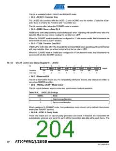
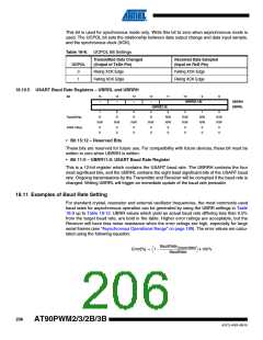
This bit is used for synchronous mode only. Write this bit to zero when asynchronous mode is
used. The UCPOL bit sets the relationship between data output change and data input sample,
and the synchronous clock (XCK).
Table 18-8. UCPOL Bit Settings
Transmitted Data Changed
(Output of TxDn Pin)
Received Data Sampled
(Input on RxD Pin)
UCPOL
0
1
Rising XCK Edge
Falling XCK Edge
Falling XCK Edge
Rising XCK Edge
18.10.5 USART Baud Rate Registers – UBRRL and UBRRH
Bit
15
14
13
12
11
10
9
8
–
–
–
–
UBRR[11:8]
UBRRH
UBRRL
UBRR[7:0]
7
R
6
R
5
R
4
R
3
R/W
R/W
0
2
R/W
R/W
0
1
R/W
R/W
0
0
R/W
R/W
0
Read/Write
Initial Value
R/W
0
R/W
0
R/W
0
R/W
0
0
0
0
0
0
0
0
0
• Bit 15:12 – Reserved Bits
These bits are reserved for future use. For compatibility with future devices, these bit must be
written to zero when UBRRH is written.
• Bit 11:0 – UBRR11:0: USART Baud Rate Register
This is a 12-bit register which contains the USART baud rate. The UBRRH contains the four
most significant bits, and the UBRRL contains the eight least significant bits of the USART baud
rate. Ongoing transmissions by the Transmitter and Receiver will be corrupted if the baud rate is
changed. Writing UBRRL will trigger an immediate update of the baud rate prescaler.
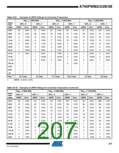
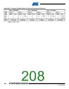
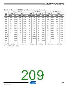
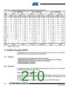
18.11 Examples of Baud Rate Setting
For standard crystal, resonator and external oscillator frequencies, the most commonly used
baud rates for asynchronous operation can be generated by using the UBRR settings in Table
18-9 up to Table 18-12. UBRR values which yield an actual baud rate differing less than 0.5%
from the target baud rate, are bold in the table. Higher error ratings are acceptable, but the
Receiver will have less noise resistance when the error ratings are high, especially for large
serial frames (see “Asynchronous Operational Range” on page 199). The error values are calcu-
lated using the following equation:
BaudRateClosest Match
⎛
⎞
Error[%] = 1 – ------------------------------------------------------- • 100%
⎝
⎠
BaudRate
206
AT90PWM2/3/2B/3B
4317J–AVR–08/10

 ATMEL [ ATMEL ]