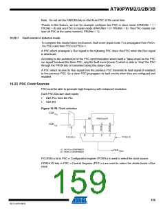
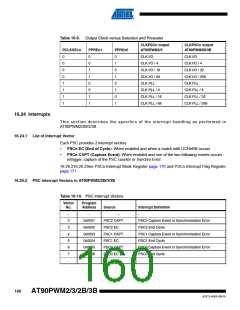
Table 16-9. Output Clock versus Selection and Prescaler
CLKPSCn output
CLKPSCn output
AT90PWM2B/3B
PCLKSELn
PPREn1
PPREn0
AT90PWM2/3
0
0
0
0
1
1
1
1
0
0
1
1
0
0
1
1
0
1
0
1
0
1
0
1
CLK I/O
CLK I/O
CLK I/O / 4
CLK I/O / 16
CLK I/O / 64
CLK PLL
CLK I/O / 4
CLK I/O / 32
CLK I/O / 256
CLK PLL
CLK PLL / 4
CLK PLL / 16
CLK PLL / 64
CLK PLL / 4
CLK PLL / 32
CLK PLL / 256
16.24 Interrupts
This section describes the specifics of the interrupt handling as performed in
AT90PWM2/2B/3/3B.
16.24.1 List of Interrupt Vector
Each PSC provides 2 interrupt vectors
•
•
PSCn EC (End of Cycle): When enabled and when a match with OCRnRB occurs
PSCn CAPT (Capture Event): When enabled and one of the two following events occurs :
retrigger, capture of the PSC counter or Synchro Error.
16.26.216.26.2See PSCn Interrupt Mask Register page 170 and PSCn Interrupt Flag Register
page 171.
16.24.2 PSC Interrupt Vectors in AT90PWM2/2B/3/3B
Table 16-10. PSC Interrupt Vectors
Vector
No.
Program
Address
Source
Interrupt Definition
-
-
-
-
2
3
4
5
6
7
-
0x0001
0x0002
0x0003
0x0004
0x0005
0x0006
-
PSC2 CAPT
PSC2 EC
PSC1 CAPT
PSC1 EC
PSC0 CAPT
PSC0 EC
-
PSC2 Capture Event or Synchronization Error
PSC2 End Cycle
PSC1 Capture Event or Synchronization Error
PSC1 End Cycle
PSC0 Capture Event or Synchronization Error
PSC0 End Cycle
-
160
AT90PWM2/3/2B/3B
4317J–AVR–08/10

 ATMEL [ ATMEL ]