AT90PWM2/3/2B/3B
16.19 PSC2 Outputs
16.19.1 Output Matrix
PSC2 has an output matrix which allow in 4 ramp mode to program a value of PSCOUT20 and
PSCOUT21 binary value for each ramp.
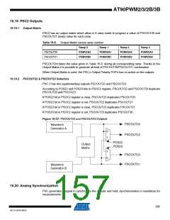
Table 16-8. Output Matrix versus ramp number
Ramp 0
Ramp 1
Ramp 2
Ramp 3
PSCOUT20
PSCOUT21
POMV2A0
POMV2B0
POMV2A1
POMV2B1
POMV2A2
POMV2B2
POMV2A3
POMV2B3
PSCOUT2m takes the value given in Table 16-8. during all corresponding ramp. Thanks to the
Output Matrix it is possible to generate all kind of PSCOUT20/PSCOUT21 combination.
When Output Matrix is used, the PSC n Output Polarity POPn has no action on the outputs.
16.19.2 PSCOUT22 & PSCOUT23 Selectors
PSC 2 has two supplementary outputs PSCOUT22 and PSCOUT23.
According to POS22 and POS23 bits in PSOC2 register, PSCOUT22 and PSCOUT23 duplicate
PSCOUT20 and PSCOU21.
If POS22 bit in PSOC2 register is clear, PSCOUT22 duplicates PSCOUT20.
If POS22 bit in PSOC2 register is set, PSCOUT22 duplicates PSCOUT21.
If POS23 bit in PSOC2 register is clear, PSCOUT23 duplicates PSCOUT21.
If POS23 bit in PSOC2 register is set, PSCOUT23 duplicates PSCOUT20.
Figure 16-37. PSCOUT22 and PSCOUT23 Outptuts
PSCOUT20
PSCOUT22
Waveform
Generator A
0
1
POS22
POS23
Output
Matrix
1
0
PSCOUT23
PSCOUT21
Waveform
Generator B
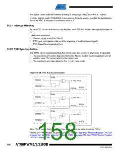
16.20 Analog Synchronization
PSC generates a signal to synchronize the sample and hold; synchronisation is mandatory for
measurements.
157
4317J–AVR–08/10

 ATMEL [ ATMEL ]