AT90PWM2/3/2B/3B
Read/Write
Initial Value
W
0
W
0
W
0
W
0
W
0
W
0
W
0
W
0
16.25.7 Output Compare RB Register – OCRnRBH and OCRnRBL
Bit
7
6
5
4
3
2
1
0
OCRnRB[15:12]
OCRnRB[11:8]
OCRnRBH
OCRnRBL
OCRnRB[7:0]
Read/Write
Initial Value
W
0
W
0
W
0
W
0
W
0
W
0
W
0
W
0
Note : n = 0 to 2 according to PSC number.
The Output Compare Registers RA, RB, SA and SB contain a 12-bit value that is continuously
compared with the PSC counter value. A match can be used to generate an Output Compare
interrupt, or to generate a waveform output on the associated pin.
The Output Compare Registers RB contains also a 4-bit value that is used for the flank width
modulation.
The Output Compare Registers are 16bit and 12-bit in size. To ensure that both the high and low
bytes are written simultaneously when the CPU writes to these registers, the access is per-
formed using an 8-bit temporary high byte register (TEMP). This temporary register is shared by
all the other 16-bit registers.
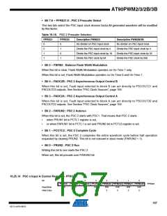
16.25.8 PSC 0 Configuration Register – PCNF0
Bit
7
PFIFTY0
R/W
0
6
5
PLOCK0
R/W
0
4
3
2
POP0
R/W
0
1
PCLKSEL0
R/W
0
-
PALOCK0
PMODE01 PMODE00
PCNF0
PCNF1
PCNF2
Read/Write
Initial Value
R/W
0
R/W
0
R/W
0
R/W
0
0
16.25.9 PSC 1 Configuration Register – PCNF1
Bit
7
PFIFTY1
R/W
0
6
5
PLOCK1
R/W
0
4
3
2
POP1
R/W
0
1
PCLKSEL1
R/W
0
-
PALOCK1
PMODE11 PMODE10
Read/Write
Initial Value
R/W
0
R/W
0
R/W
0
R/W
0
0
16.25.10 PSC 2 Configuration Register – PCNF2
Bit
7
PFIFTY2
R/W
0
6
5
PLOCK2
R/W
0
4
3
2
POP2
R/W
0
1
PCLKSEL2
R/W
0
PALOCK2
POME2
PMODE21 PMODE20
Read/Write
Initial Value
R/W
0
R/W
0
R/W
0
R/W
0
0
The PSC n Configuration Register is used to configure the running mode of the PSC.
• Bit 7 - PFIFTYn: PSC n Fifty
Writing this bit to one, set the PSC in a fifty percent mode where only OCRnRBH/L and OCRn-
SBH/L are used. They are duplicated in OCRnRAH/L and OCRnSAH/L during the update of
OCRnRBH/L. This feature is useful to perform fifty percent waveforms.
• Bit 6 - PALOCKn: PSC n Autolock
When this bit is set, the Output Compare Registers RA, SA, SB, the Output Matrix POM2 and
the PSC Output Configuration PSOCn can be written without disturbing the PSC cycles. The
163
4317J–AVR–08/10

 ATMEL [ ATMEL ]