AT89S8252
programming is still in progress and RDY/BSY = 1 means EEPROM write cycle is com-
pleted and another write cycle can be initiated.
In addition, during EEPROM programming, an attempted read from the EEPROM will
fetch the byte being written with the MSB complemented. Once the write cycle is com-
pleted, true data are valid at all bit locations.
Programmable
Watchdog Timer
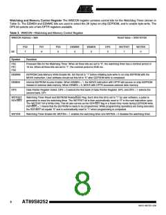
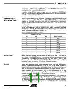
The programmable Watchdog Timer (WDT) operates from an independent internal
oscillator. The prescaler bits, PS0, PS1 and PS2 in SFR WMCON are used to set the
period of the Watchdog Timer from 16 ms to 2048 ms. The available timer periods are
shown in the following table and the actual timer periods (at VCC = 5V) are within 30%
of the nominal.
The WDT is disabled by Power-on Reset and during Power-down. It is enabled by set-
ting the WDTEN bit in SFR WMCON (address = 96H). The WDT is reset by setting the
WDTRST bit in WMCON. When the WDT times out without being reset or disabled, an
internal RST pulse is generated to reset the CPU.
Table 7. Watchdog Timer Period Selection
WDT Prescaler Bits
PS2
0
PS1
0
PS0
0
Period (nominal)
16 ms
0
0
1
32 ms
0
1
0
64 ms
0
1
1
128 ms
1
0
0
256 ms
1
0
1
512 ms
1
1
0
1024 ms
2048 ms
1
1
1
Timer 0 and 1
Timer 2
Timer 0 and Timer 1 in the AT89S8252 operate the same way as Timer 0 and Timer 1 in
the AT89C51 and AT89C52. For further information on the timers’ operation, refer to the
Atmel web site (http://www.atmel.com). From the home page, select “Products”, then
“Microcontrollers, then “8051-Architecture”. Click on “Documentation”, then on “Other
Documents”. Open the document “AT89 Series Hardware Description”.
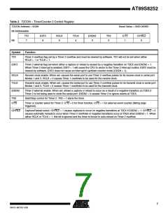
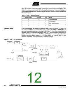
Timer 2 is a 16-bit Timer/Counter that can operate as either a timer or an event counter.
The type of operation is selected by bit C/T2 in the SFR T2CON (shown in Table 2).
Timer 2 has three operating modes: capture, auto-reload (up or down counting), and
baud rate generator. The modes are selected by bits in T2CON, as shown in Table 8.
Timer 2 consists of two 8-bit registers, TH2 and TL2. In the Timer function, the TL2 reg-
ister is incremented every machine cycle. Since a machine cycle consists of 12
oscillator periods, the count rate is 1/12 of the oscillator frequency.
In the Counter function, the register is incremented in response to a 1-to-0 transition at
its corresponding external input pin, T2. In this function, the external input is sampled
during S5P2 of every machine cycle. When the samples show a high in one cycle and a
low in the next cycle, the count is incremented. The new count value appears in the reg-
ister during S3P1 of the cycle following the one in which the transition was detected.
11
0401G–MICRO–3/06

 ATMEL [ ATMEL ]