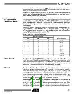
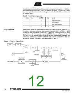
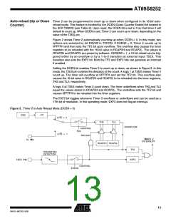
AT89S8252
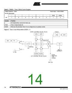
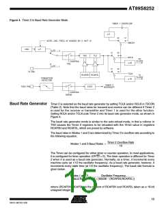
Figure 4. Timer 2 in Baud Rate Generator Mode
TIMER 1 OVERFLOW
2
÷
"0"
"0"
"1"
NOTE: OSC. FREQ. IS DIVIDED BY 2, NOT 12
SMOD1
2
OSC
÷
C/T2 = 0
"1"
"1"
TH2
TL2
RCLK
Rx
CLOCK
CONTROL
TR2
16
÷
C/T2 = 1
"0"
T2 PIN
TCLK
Tx
RCAP2H RCAP2L
CLOCK
TRANSITION
DETECTOR
16
÷
TIMER 2
INTERRUPT
T2EX PIN
EXF2
CONTROL
EXEN2
Baud Rate Generator Timer 2 is selected as the baud rate generator by setting TCLK and/or RCLK in T2CON
(Table 2). Note that the baud rates for transmit and receive can be different if Timer 2
is used for the receiver or transmitter and Timer 1 is used for the other function.
Setting RCLK and/or TCLK puts Timer 2 into its baud rate generator mode, as shown in
Figure 4.
The baud rate generator mode is similar to the auto-reload mode, in that a rollover in
TH2 causes the Timer 2 registers to be reloaded with the 16-bit value in registers
RCAP2H and RCAP2L, which are preset by software.
The baud rates in Modes 1 and 3 are determined by Timer 2’s overflow rate according to
the following equation.
Timer 2 Overflow Rate
Modes 1 and 3 Baud Rates = -----------------------------------------------------------
16
The Timer can be configured for either timer or counter operation. In most applications,
it is configured for timer operation (CP/T2 = 0). The timer operation is different for Timer
2 when it is used as a baud rate generator. Normally, as a timer, it increments every
machine cycle (at 1/12 the oscillator frequency). As a baud rate generator, however, it
increments every state time (at 1/2 the oscillator frequency). The baud rate formula is
given below.
Modes 1 and 3
Baud Rate 32 × [65536 – (RCAP2H,RCAP2L)]
Oscillator Frequency
--------------------------------------- = ----------------------------------------------------------------------------------------------
where (RCAP2H, RCAP2L) is the content of RCAP2H and RCAP2L taken as a 16-bit
unsigned integer.
15
0401G–MICRO–3/06

 ATMEL [ ATMEL ]