Since two machine cycles (24 oscillator periods) are required to recognize a 1-to-0 tran-
sition, the maximum count rate is 1/24 of the oscillator frequency. To ensure that a given
level is sampled at least once before it changes, the level should be held for at least one
full machine cycle.
Table 8. Timer 2 Operating Modes
RCLK + TCLK
CP/RL2
TR2
1
MODE
0
0
1
X
0
1
16-bit Auto-reload
16-bit Capture
Baud Rate Generator
(Off)
1
X
X
1
0
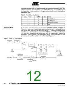
Capture Mode
In the capture mode, two options are selected by bit EXEN2 in T2CON. If EXEN2 = 0,
Timer 2 is a 16-bit timer or counter which upon overflow sets bit TF2 in T2CON. This bit
can then be used to generate an interrupt. If EXEN2 = 1, Timer 2 performs the same
operation, but a l-to-0 transition at external input T2EX also causes the current value in
TH2 and TL2 to be captured into RCAP2H and RCAP2L, respectively. In addition, the
transition at T2EX causes bit EXF2 in T2CON to be set. The EXF2 bit, like TF2, can
generate an interrupt. The capture mode is illustrated in Figure 1.
Figure 1. Timer 2 in Capture Mode
÷12
OSC
C/T2 = 0
TH2
TL2
TF2
OVERFLOW
CONTROL
TR2
C/T2 = 1
CAPTURE
T2 PIN
RCAP2H RCAP2L
EXF2
TRANSITION
DETECTOR
TIMER 2
INTERRUPT
T2EX PIN
CONTROL
EXEN2
12
AT89S8252
0401G–MICRO–3/06

 ATMEL [ ATMEL ]