15.1.3
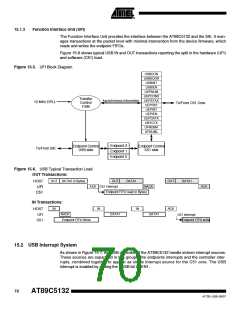
Function Interface Unit (UFI)
The Function Interface Unit provides the interface between the AT89C5132 and the SIE. It man-
ages transactions at the packet level with minimal intervention from the device firmware, which
reads and writes the endpoint FIFOs.
Figure 15-6 shows typical USB IN and OUT transactions reporting the split in the hardware (UFI)
and software (C51) load.
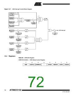
Figure 15-5. UFI Block Diagram
USBCON
USBADDR
USBINT
USBIEN
UEPNUM
UEPCONX
UEPSTAX
UEPRST
UEPINT
Transfer
Control
FSM
Asynchronous Information
12 MHz DPLL
To/From C51 Core
UEPIEN
UEPDATX
UBYCTX
UFNUMH
UFNUML
Endpoint 2
Endpoint 1
Endpoint 0
Endpoint Control
USB side
Endpoint Control
C51 side
To/From SIE
Figure 15-6. USB Typical Transaction Load
OUT Transactions:
OUT DATA0 (n Bytes)
OUT
DATA1
OUT
DATA1
HOST
UFI
ACK C51 interrupt
NACK
ACK
Endpoint FIFO read (n Bytes)
C51
IN Transactions:
IN
IN
IN
ACK
HOST
NACK
Endpoint FIFO Write
DATA1
DATA1
UFI
C51 interrupt
Endpoint FIFO write
C51
15.2 USB Interrupt System
As shown in Figure 15-7, the USB controller of the AT89C5132 handle sixteen interrupt sources.
These sources are separated in two groups: the endpoints interrupts and the controller inter-
rupts, combined together to appear as single interrupt source for the C51 core. The USB
interrupt is enabled by setting the EUSB bit in IEN1.
70
AT89C5132
4173E–USB–09/07

 ATMEL [ ATMEL ]