AT89C5132
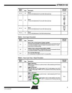
Table 7. UART Signal Description
Signal
Alternate
Function
Name
Type
Description
Receive Serial Data
RXD sends and receives data in serial I/O mode 0 and receives data in serial
I/O modes 1, 2 and 3.
RXD
I/O
P3.0
P3.1
Transmit Serial Data
TXD
O
TXD outputs the shift clock in serial I/O mode 0 and transmits data in serial I/O
modes 1, 2 and 3.
Table 8. SPI Controller Signal Description
Signal
Name
Alternate
Function
Type
Description
SPI Master Input Slave Output Data Line
When in master mode, MISO receives data from the slave peripheral. When in
slave mode, MISO outputs data to the master controller.
MISO
I/O
P4.0
P4.1
SPI Master Output Slave Input Data Line
When in master mode, MOSI outputs data to the slave peripheral. When in
slave mode, MOSI receives data from the master controller.
MOSI
I/O
SPI Clock Line
SCK
SS
I/O
I
When in master mode, SCK outputs clock to the slave peripheral. When in
slave mode, SCK receives clock from the master controller.
P4.2
P4.3
SPI Slave Select Line
When in controlled slave mode, SS enables the slave mode.
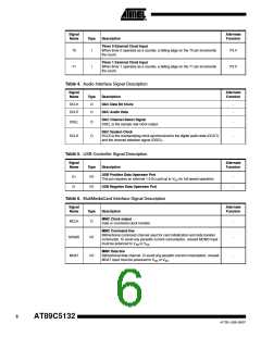
Table 9. TWI Controller Signal Description
Signal
Name
Alternate
Function
Type
Description
TWI Serial Clock
When TWI controller is in master mode, SCL outputs the serial clock to the
slave peripherals. When TWI controller is in slave mode, SCL receives clock
from the master controller.
SCL
I/O
P1.6
P1.7
TWI Serial Data
SDA
I/O
SDA is the bidirectional Two Wire data line.
Table 10. A/D Converter Signal Description
Signal
Alternate
Function
Name
AIN1:0
AREFP
Type
Description
I
I
A/D Converter Analog Inputs
Analog Positive Voltage Reference Input
-
-
Analog Negative Voltage Reference Input
This pin is internally connected to AVSS.
AREFN
I
-
7
4173E–USB–09/07

 ATMEL [ ATMEL ]