22. Keyboard Interface
The AT89C5132 implements a keyboard interface allowing the connection of a 4 x n matrix key-
board. It is based on 4 inputs with programmable interrupt capability on both high or low level.
These inputs are available as alternate function of P1.3:0 and allow exit from idle and power
down modes.
22.1 Description
The keyboard interfaces with the C51 core through two special function registers: KBCON, the
keyboard control register (see Table 101); and KBSTA, the keyboard control and status register
(see Table 102).
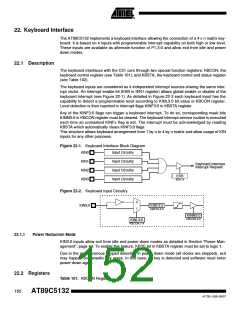
The keyboard inputs are considered as 4 independent interrupt sources sharing the same inter-
rupt vector. An interrupt enable bit (EKB in IEN1 register) allows global enable or disable of the
keyboard interrupt (see Figure 22-1). As detailed in Figure 22-2 each keyboard input has the
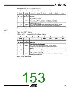
capability to detect a programmable level according to KINL3:0 bit value in KBCON register.
Level detection is then reported in interrupt flags KINF3:0 in KBSTA register.
Any of the KINF3:0 flags can trigger a keyboard interrupt. To do so, corresponding mask bits
KINM3:0 in KBCON register must be cleared. The keyboard interrupt service routine is executed
each time an unmasked KINFx flag is set. The interrupt must be acknowledged by reading
KBSTA which automatically clears KINF3:0 flags.
This structure allows keyboard arrangement from 1 by n to 4 by n matrix and allow usage of KIN
inputs for any other purposes.
Figure 22-1. Keyboard Interface Block Diagram
KIN0
KIN1
KIN2
KIN3
Input Circuitry
Input Circuitry
Input Circuitry
Input Circuitry
Keyboard Interface
Interrupt Request
EKB
IEN1.4
Figure 22-2. Keyboard Input Circuitry
0
1
KIN3:0
KINF3:0
KBSTA.3:0
KINM3:0
KBCON.3:0
KINL3:0
KBCON.7:4
22.1.1
Power Reduction Mode
KIN3:0 inputs allow exit from idle and power down modes as detailed in Section “Power Man-
agement”, page 44. To enable this feature, KPDE bit in KBSTA register must be set to logic 1.
Due to the asynchronous keypad detection in power down mode (all clocks are stopped), exit
may happen on parasitic key press. In this case, no key is detected and software must enter
power-down again.
22.2 Registers
Table 101. KBCON Register
152
AT89C5132
4173E–USB–09/07

 ATMEL [ ATMEL ]