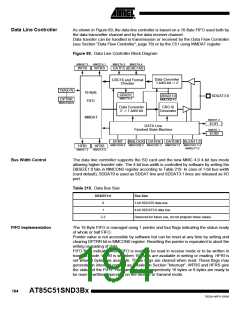
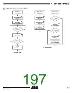
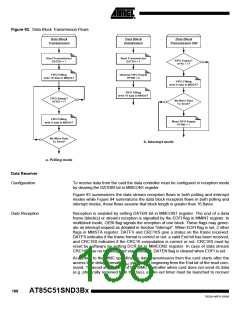
Figure 92. Data Block Transmission Flows
Data Block
Data Block
Data Block
Transmission
Initialization
Transmission ISR
Start Transmission
Start Transmission
FIFO Empty?
HFRI = 1?
DATEN = 1
DATEN = 1
FIFO Filling
Unmask FIFO Empty
write 16 data to MMDAT
HFRM = 0
FIFO Filling
write 8 data to MMDAT
FIFO Filling
write 16 data to MMDAT
FIFO Empty?
No More Data
To Send?
HFRS = 1?
FIFO Filling
write 8 data to MMDAT
Mask FIFO Empty
HFRM = 1
No More Data
To Send?
b. Interrupt mode
a. Polling mode
Data Receiver
Configuration
To receive data from the card the data controller must be configured in reception mode
by clearing the DATDIR bit in MMCON1 register.
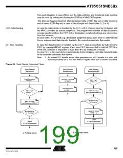
Figure 93 summarizes the data stream reception flows in both polling and interrupt
modes while Figure 94 summarizes the data block reception flows in both polling and
interrupt modes, these flows assume that block length is greater than 16 Bytes.
Data Reception
Reception is enabled by setting DATEN bit in MMCON1 register. The end of a data
frame (block(s) or stream) reception is signalled by the EOFI flag in MMINT register. In
multiblock mode, OEBI flag signals the reception of one block. These flags may gener-
ate an interrupt request as detailed in Section “Interrupt”. When EOFI flag is set, 2 other
flags in MMSTA register: DATFS and CRC16S give a status on the frame received.
DATFS indicates if the frame format is correct or not: a valid End bit has been received,
and CRC16S indicates if the CRC16 computation is correct or not. CRC16S must by
reset by software by setting DCR bit in MMCON2 register. In case of data stream
CRC16S has no meaning and stays cleared. DATEN flag is cleared when EOFI is set.
According to the MMC specification data transmission from the card starts after the
access time delay (formally NAC parameter) beginning from the End bit of the read com-
mand. To avoid any locking of the MMC controller when card does not send its data
(e.g. physically removed from the bus), a time-out timer must be launched to recover
198
AT85C51SND3Bx
7632A–MP3–03/06

 ATMEL [ ATMEL ]