AT85C51SND3Bx
from such situation. In case of time-out, the data controller and its internal state machine
may be reset by setting and clearing the DCR bit in MMCON2 register.
This time-out may be disarmed after receiving 8 data (HFRS flag set) or after receiving
end of frame (EOFI flag set) in case of block length less than 8 data (1, 2 or 4).
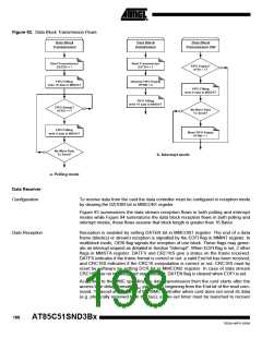
DFC Data Reading
C51 Data Reading
In case the data transfer is handled by the DFC, a DFC channel must be configured with
the MMC controller as source peripheral. The programmed number of data is autono-
mously transferred from the FIFO to the destination peripheral without any intervention
from the firmware.
In case both FIFO are full (e.g. destination peripheral busy), card clock is automatically
frozen stopping card data transfer thanks to the controller automatic flow control.
In case the data transfer is handled by the C51(1), data is read byte by byte from the
FIFO by reading MMDAT register. Each time FIFO becomes full or half full (WFRI or
HFRI set), software is requested to flush this FIFO by reading 16 or 8data.
In case FIFO is full, card clock is automatically frozen stopping card data transfer thanks
to the controller automatic flow control.
Note:
1. An enabled DFC transfer always takes precedence on a C51 transfer, it is under soft-
ware responsibility not to read from MMDAT register while a DFC transfer is enabled.
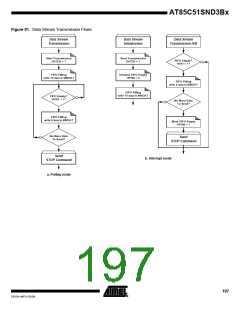
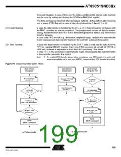
Figure 93. Data Stream Reception Flows
Data Stream
Reception
Data Stream
Initialization
Data Stream
Reception ISR
Start Reception
DATEN = 1
Unmask FIFO Full
FIFO Full?
HFRI = 1?
HFRM = 0
Start Reception
DATEN = 1
FIFO Reading
read 8 data from MMDAT
FIFO Full?
HFRS = 1?
No More Data
To Receive?
FIFO Reading
read 8 data from MMDAT
Mask FIFO Full
HFRM = 1
No More Data
To Receive?
Send
STOP Command
Send
STOP Command
b. Interrupt mode
a. Polling mode
199
7632A–MP3–03/06

 ATMEL [ ATMEL ]