AT8xC51SND2C
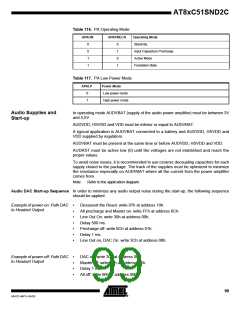
Table 116. PA Operating Mode
APAON
APAPRECH
Operating Mode
Stand-By
0
0
1
1
0
1
0
1
Input Capacitors Precharge
Active Mode
Forbidden State
Table 117. PA Low Power Mode
APALP
Power Mode
0
1
Low power mode
High power mode
Audio Supplies and
Start-up
In operating mode AUDVBAT (supply of the audio power amplifier) must be between 3V
and 5,5V.
AUDVDD, HSVDD and VDD must be inferior or equal to AUDVBAT.
A typical application is AUDVBAT connected to a battery and AUDVDD, HSVDD and
VDD supplied by regulators.
AUDVBAT must be present at the same time or before AUDVDD, HSVDD and VDD.
AUDRST must be active low (0) until the voltages are not etablished and reach the
proper values.
To avoid noise issues, it is recommended to use ceramic decoupling capacitors for each
supply closed to the package. The track of the supplies must be optimized to minimize
the resistance especially on AUDVBAT where all the current from the power amplifier
comes from.
Note:
Refer to the application diagram.
Audio DAC Start-up Sequence In order to minimize any audio output noise during the start-up, the following sequence
should be applied.
Example of power-on: Path DAC
to Headset Output
•
•
•
•
•
•
•
Desassert the Reset: write 07h at address 10h.
All precharge and Master on: write FFh at address 0Ch.
Line Out On: write 30h at address 00h.
Delay 500 ms.
Precharge off: write 0Ch at address 01h.
Delay 1 ms.
Line Out on, DAC On: write 3Ch at address 00h.
Example of power-off: Path DAC
to Headset Output
•
•
•
•
DAC off: write 30h at address 00h.
Master off: write 00h at address 0Ch.
Delay 1 ms.
All off: write 00h at address 00h
99
4341D–MP3–04/05

 ATMEL [ ATMEL ]