Keyboard Interface
The AT8xC51SND2C implement a keyboard interface allowing the connection of a key-
pad. It is based on one input with programmable interrupt capability on both high or low
level. This input allows exit from idle and power down modes.
Description
The keyboard interfaces with the C51 core through 2 special function registers: KBCON,
the keyboard control register (see Table 179); and KBSTA, the keyboard control and
status register (see Table 180).
An interrupt enable bit (EKB in IEN1 register) allows global enable or disable of the key-
board interrupt (see Figure 137). As detailed in Figure 138 this keyboard input has the
capability to detect a programmable level according to KINL0 bit value in KBCON regis-
ter. Level detection is then reported in interrupt flag KINF0 in KBSTA register.
A keyboard interrupt is requested each time this flag is set. This flag can be masked by
software using KINM0 bits in KBCON register and is cleared by reading KBSTA register.
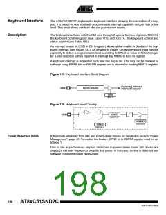
Figure 137. Keyboard Interface Block Diagram
Keyboard Interface
Interrupt Request
KIN0
Input Circuitry
EKB
IEN1.4
Figure 138. Keyboard Input Circuitry
0
1
KIN0
KINF0
KBSTA.0
KINM0
KBCON.0
KINL0
KBCON.4
Power Reduction Mode
KIN0 inputs allow exit from idle and power-down modes as detailed in section “Power
Management”, page 46. To enable this feature, KPDE bit in KBSTA register must be set
to logic 1.
Due to the asynchronous keypad detection in power down mode (all clocks are
stopped), exit may happen on parasitic key press. In this case, no key is detected and
software must enter power down again.
198
AT8xC51SND2C
4341D–MP3–04/05

 ATMEL [ ATMEL ]