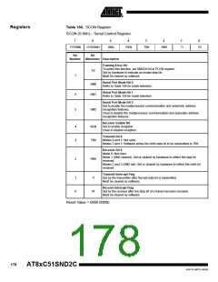
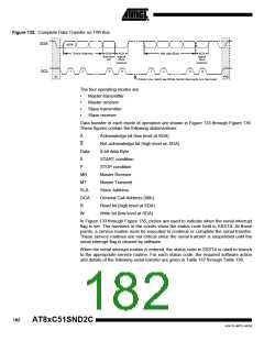
Figure 132. Complete Data Transfer on TWI Bus
SDA
MSB
Slave Address
R/W
ACK
Nth data Byte
ACK
signal
from
direction signal
bit
from
receiver
receiver
1
2
8
9
1
2
8
9
SCL
S
P/S
Clock Line Held Low While Serial Interrupts Are Serviced
The four operating modes are:
•
•
•
•
Master transmitter
Master receiver
Slave transmitter
Slave receiver
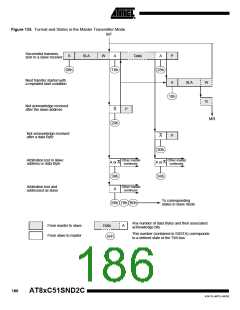
Data transfer in each mode of operation are shown in Figure 133 through Figure 136.
These figures contain the following abbreviations:
A
Acknowledge bit (low level at SDA)
Not acknowledge bit (high level on SDA)
8-bit data Byte
A
Data
S
START condition
P
STOP condition
MR
MT
SLA
GCA
R
Master Receive
Master Transmit
Slave Address
General Call Address (00h)
Read bit (high level at SDA)
Write bit (low level at SDA)
W
In Figure 133 through Figure 136, circles are used to indicate when the serial interrupt
flag is set. The numbers in the circles show the status code held in SSSTA. At these
points, a service routine must be executed to continue or complete the serial transfer.
These service routines are not critical since the serial transfer is suspended until the
serial interrupt flag is cleared by software.
When the serial interrupt routine is entered, the status code in SSSTA is used to branch
to the appropriate service routine. For each status code, the required software action
and details of the following serial transfer are given in Table 167 through Table 136.
182
AT8xC51SND2C
4341D–MP3–04/05

 ATMEL [ ATMEL ]