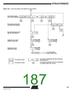
Master Receiver Mode
In the master receiver mode, a number of data Bytes are received from a slave transmit-
ter (see Figure 134). The transfer is initialized as in the master transmitter mode. When
the START condition has been transmitted, the interrupt routine must load SSDAT with
the 7 - bit slave address and the data direction bit (SLA+R). The serial interrupt flag
(SSI) must then be cleared before the serial transfer can continue.
When the slave address and the direction bit have been transmitted and an acknowl-
edgment bit has been received, the serial interrupt flag is set again and a number of
status code in SSSTA are possible. There are 40h, 48h or 38h for the master mode and
also 68h, 78h or B0h if the slave mode was enabled (SSAA = logic 1). The appropriate
action to be taken for each of these status code is detailed in Table 136. This scheme is
repeated until a STOP condition is transmitted.
SSPE and SSCR2:0 are not affected by the serial transfer and are not referred to in
Table 136. After a repeated START condition (state 10h) the controller may switch to
the master transmitter mode by loading SSDAT with SLA+W.
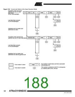
Slave Receiver Mode
In the slave receiver mode, a number of data Bytes are received from a master transmit-
ter (see Figure 135). To initiate the slave receiver mode, SSADR and SSCON must be
loaded as follows:
SSA6
SSA5
SSA4
SSA3
SSA2
SSA1
SSA0
SSGC
X
←⎯⎯⎯⎯⎯⎯⎯⎯⎯⎯
Own Slave Address
⎯⎯⎯⎯⎯⎯⎯⎯⎯⎯→
The upper 7 bits are the addresses to which the controller will respond when addressed
by a master. If the LSB (SSGC) is set, the controller will respond to the general call
address (00h); otherwise, it ignores the general call address.
SSCR2
X
SSPE
1
SSSTA
0
SSSTO
0
SSI
0
SSAA
1
SSCR1
X
SSCR0
X
SSCR2:0 have no effect in the slave mode. SSPE must be set to enable the controller.
The SSAA bit must be set to enable the own slave address or the general call address
acknowledgment. SSSTA, SSSTO and SSI must be cleared.
When SSADR and SSCON have been initialized, the controller waits until it is
addressed by its own slave address followed by the data direction bit which must be
logic 0 (W) for operating in the slave receiver mode. After its own slave address and the
W bit has been received, the serial interrupt flag is set and a valid status code can be
read from SSSTA. This status code is used to vector to an interrupt service routine, and
the appropriate action to be taken for each of these status code is detailed in Table 136
and Table 171. The slave receiver mode may also be entered if arbitration is lost while
the controller is in the master mode (see states 68h and 78h).
If the SSAA bit is reset during a transfer, the controller will return a not acknowledge
(logic 1) to SDA after the next received data Byte. While SSAA is reset, the controller
does not respond to its own slave address. However, the TWI bus is still monitored and
address recognition may be resumed at any time by setting SSAA. This means that the
SSAA bit may be used to temporarily isolate the controller from the TWI bus.
184
AT8xC51SND2C
4341D–MP3–04/05

 ATMEL [ ATMEL ]