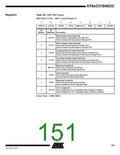
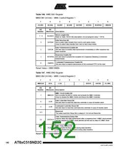
Table 146. MMCON1 Register
MMCON1 (S:E5h) – MMC Control Register 1
7
6
5
4
3
2
1
0
BLEN3
BLEN2
BLEN1
BLEN0
DATDIR
DATEN
RESPEN
CMDEN
Bit
Bit
Number
Mnemonic Description
Block Length Bits
Refer to Table 144 for bits description. Do not program value > 1011b
7 - 4
3
BLEN3:0
Data Direction Bit
DATDIR Set to select data transfer from host to card (write mode).
Clear to select data transfer from card to host (read mode).
Data Transmission Enable Bit
2
DATEN
Set and clear to enable data transmission immediately or after response has
been received.
Response Enable Bit
1
0
RESPEN Set and clear to enable the reception of a response following a command
transmission.
Command Transmission Enable Bit
CMDEN
Set and clear to enable transmission of the command FIFO to the card.
Reset Value = 0000 0000b
Table 147. MMCON2 Register
MMCON2 (S:E6h) – MMC Control Register 2
7
6
5
4
-
3
-
2
1
0
MMCEN
DCR
CCR
DATD1
DATD0
FLOWC
Bit
Bit
Number
Mnemonic Description
MMC Clock Enable Bit
7
MMCEN Set to enable the MCLK clocks and activate the MMC controller.
Clear to disable the MMC clocks and freeze the MMC controller.
Data Controller Reset Bit
Set and clear to reset the data line controller in case of transfer abort.
6
5
DCR
Command Controller Reset Bit
Set and clear to reset the command line controller in case of transfer abort.
CCR
Reserved
4-3
-
The value read from these bits is always 0. Do not set these bits.
Data Transmission Delay Bits
Used to delay the data transmission after a response from 3 MMC clock periods
(all bits cleared) to 9 MMC clock periods (all bits set) by step of 2 MMC clock
periods.
2-1
0
DATD1:0
MMC Flow Control Bit
FLOWC Set to enable the flow control during data transfers.
Clear to disable the flow control during data transfers.
Reset Value = 0000 0000b
152
AT8xC51SND2C
4341D–MP3–04/05

 ATMEL [ ATMEL ]