AT8xC51SND2C
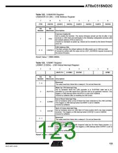
Table 122. USBADDR Register
USBADDR (S:C6h) – USB Address Register
7
6
5
4
3
2
1
0
FEN
UADD6
UADD5
UADD4
UADD3
UADD2
UADD1
UADD0
Bit
Bit
Number
Mnemonic Description
Function Enable Bit
Set to enable the function. The device firmware should set this bit after it has
received a USB reset and participate in the following configuration process with
the default address (FEN is reset to 0).
7
FEN
Cleared by hardware at power-up, should not be cleared by the device firmware
once set.
USB Address Bits
This field contains the default address (0) after power-up or USB bus reset.
It should be written with the value set by a SET_ADDRESS request received by
the device firmware.
6 - 0
UADD6:0
Reset Value = 0000 0000b
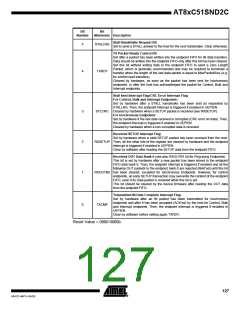
Table 123. USBINT Register
USBINT (S:BDh) – USB Global Interrupt Register
7
-
6
-
5
4
3
2
-
1
-
0
WUPCPU
EORINT
SOFINT
SPINT
Bit
Bit
Number
Mnemonic Description
Reserved
7 - 6
-
The value read from these bits is always 0. Do not set these bits.
Wake Up CPU Interrupt Flag
Set by hardware when the USB controller is in SUSPEND state and is re-
WUPCPU activated by a non-idle signal from USB line (not by an upstream resume). This
triggers a USB interrupt when EWUPCPU is set in the USBIEN.
5
Cleared by software after re-enabling all USB clocks.
End of Reset Interrupt Flag
Set by hardware when a End of Reset has been detected by the USB controller.
This triggers a USB interrupt when EEORINT is set in USBIEN.
4
EORINT
Cleared by software.
Start of Frame Interrupt Flag
Set by hardware when an USB Start of Frame packet (SOF) has been properly
received. This triggers a USB interrupt when ESOFINT is set in USBIEN.
3
SOFINT
Cleared by software.
Reserved
2 - 1
-
The value read from these bits is always 0. Do not set these bits.
Suspend Interrupt Flag
Set by hardware when a USB Suspend (Idle bus for three frame periods: a J
0
SPINT
state for 3 ms) is detected. This triggers a USB interrupt when ESPINT is set in
USBIEN.
Cleared by software.
Reset Value = 0000 0000b
123
4341D–MP3–04/05

 ATMEL [ ATMEL ]