Application Notes
ATH10T03 & ATH10T05 Series
Adjusting the Output Voltage of the ATH10T033
& ATH10T05 Wide-Output Adjust Power Modules
Table 1-2; Output Voltage Set-Point Resistor Values
The Vo Adjust control (pin 4) sets the output voltage of the
ATH10T033 and ATH10T05 products to a value higher than
0.8 V. The adjustment range of the ATH10T033 (3.3-V
Va Req’d
Rset
Va Req’d
Rset
2.00
2.05
2.10
2.15
2.20
2.25
2.30
2.35
2.40
2.45
2.50
2.55
2.60
2.65
2.70
2.75
2.80
2.85
2.90
2.95
3.00
3.05
3.10
3.15
3.20
3.25
3.30
3.35
3.40
3.45
3.50
3.55
3.60
4.18 kΩ
3.91 kΩ
3.66 kΩ
3.44 kΩ
3.22 kΩ
3.03 kΩ
2.84 kΩ
2.67 kΩ
2.51 kΩ
2.36 kΩ
2.22 kΩ
2.08 kΩ
1.95 kΩ
1.83 kΩ
1.72 kΩ
1.61 kΩ
1.51 kΩ
1.41 kΩ
1.32 kΩ
1.23 kΩ
1.15 kΩ
1.07 kΩ
988 Ω
0.800
0.825
0.850
0.875
0.900
0.925
0.950
0.975
1.000
1.025
1.050
1.075
1.100
1.125
1.150
1.175
1.200
1.225
1.250
1.275
1.300
1.325
1.350
1.375
1.400
1.425
1.450
1.475
1.50
Open
1
input) is from 0.8 V to 2.5 V , and the ATH10T05 (5-V input)
318 kΩ
158 kΩ
104 kΩ
77.5 kΩ
61.5 kΩ
50.8 kΩ
43.2 kΩ
37.5 kΩ
33.1 kΩ
29.5 kΩ
26.6 kΩ
24.2 kΩ
22.1 kΩ
20.4 kΩ
18.8 kΩ
17.5 kΩ
16.3 kΩ
15.3 kΩ
14.4 kΩ
13.5 kΩ
12.7 kΩ
12.1 kΩ
11.4 kΩ
10.8 kΩ
10.3 kΩ
9.82 kΩ
9.36 kΩ
8.94 kΩ
8.18 kΩ
7.51 kΩ
6.92 kΩ
6.4 kΩ
from 0.8 V to 3.6 V. For an output voltage other than
0.8 V a single external resistor, Rset, must be connected
2
directly between the Vo Adjust and GND pins . Table 1-1
gives the preferred value of the external resistor for a num-
ber of standard voltages, along with the actual output
voltage that this resistance value provides.
For other output voltages the value of the required resistor
can either be calculated using the following formula, or
simply selected from the range of values given in Table 1-2.
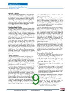
Figure 1-1 shows the placement of the required resistor.
0.8 V
Vout – 0.8 V
Rset
= 10 kΩ ·
– 2.49 kΩ
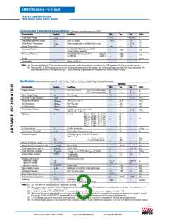
Table 1-1; Preferred Values of Rset for Standard Output Voltages
Vout (Standard)
Rset (Pref’d Value)
Vout (Actual)
1
3.3 V
2.5 V
2 V
1.8 V
1.5 V
1.2 V
1 V
698 Ω
3.309V
2.502 V
2.010 V
1.803 V
1.504 V
1.202 V
1.005 V
0.8 V
914 Ω
843 Ω
775 Ω
710 Ω
647 Ω
587 Ω
529 Ω
473 Ω
2.21 kΩ
4.12 kΩ
5.49 kΩ
8.87 kΩ
17.4 kΩ
36.5 kΩ
Open
1.55
1.60
1.65
1.70
0.8 V
419 Ω
367 Ω
1.75
1.80
1.85
1.90
5.93 kΩ
5.51 kΩ
5.13 kΩ
4.78 kΩ
4.47 kΩ
Figure 1-1; Vo Adjust Resistor Placement
Vo Sense
1.95
10
9
8
5
Notes:
VIN
VOUT
2
6
1. Modules that operate from a 3.3-V input bus should
not be adjusted higher than 2.5 V.
PTH05060W
ATH10T05-9S
3
1
7
4
2. Use a 0.1 W resistor. The tolerance should be 1 %, with
temperature stability of 100 ppm/°C (or better). Place
the resistor as close to the regulator as possible. Connect
the resistor directly between pins 4 and 7 using dedicated
PCB traces.
RSET
0.1 W
1 %
+
+
CIN
330 µF
COUT
330 µF
(Optional)
(Required)
3. Never connect capacitors from Vo Adjust to either GND or
Vout. Any capacitance added to the Vo Adjust pin will affect
the stability of the regulator.
GND
North America (USA): 1-888-41-ASTEC
Europe (UK): 44(1384)842-211
Asia (HK): 852-2437-9662

 ASTEC [ Astec America, Inc ]