Application Notes
ATH Series of Wide-Output Adjust Power
Modules (3.3/5-V Input)
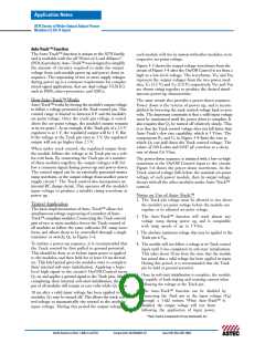
Auto-Track™ Function
The Auto-Track™ function is unique to the ATH family,
and is available with the all “Point-of-Load Alliance”
(POLA) products. Auto-Track™ was designed to simplify
the amount of circuitry required to make the output
voltage from each module power up and power down in
sequence. The sequencing of two or more supply voltages
during power up is a common requirement for complex
mixed-signal applications, that use dual-voltage VLSI ICs
such as DSPs, micro-processors, and ASICs.
each module will rise in unison with other modules, to its
respective set-point voltage.
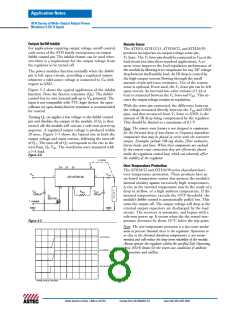
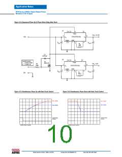
Figure 3-5 shows the output voltage waveforms from the
circuit of Figure 3-4 after the On/Off Control is set from a
high to a low-level voltage. The waveforms, Vo1 and Vo2
represent the output voltages from the two power mod-
ules, U1 (3.3 V) and U2 (2.0 V) respectively. Vo1 and Vo2
are shown rising together to produce the desired simul-
taneous power-up characteristic.
How Auto-Track™ Works
The same circuit also provides a power-down sequence.
Power down is the reverse of power up, and is accom-
plished by lowering the track control voltage back to zero
volts. The important constraint is that a valid input voltage
must be maintained until the power down is complete. It
also requires that Q1 be turned off relatively slowly. This
is so that the Track control voltage does not fall faster than
Auto-Track's slew rate capability, which is 5 V/ms. The
components R1 and C1 in Figure 3-4 limit the rate at
which Q1 can pull down the Track control voltage. The
values of 100 k-ohm and 0.047 µF correlate to a decay
rate of about 0.6 V/ms.
Auto-Track™ works by forcing the module’s output voltage
to follow a voltage presented at the Track control pin. This
control range is limited to between 0 V and the module’s
set-point voltage. Once the track-pin voltage is raised
above the set-point voltage, the module’s output remains
1
at its set-point . As an example, if the Track pin of a 2.5-V
regulator is at 1 V, the regulated output will be 1 V. But
if the voltage at the Track pin rises to 3 V, the regulated
output will not go higher than 2.5 V.
When under track control, the regulated output from
the module follows the voltage at its Track pin on a volt-
for-volt basis. By connecting the Track pin of a number
of these modules together, the output voltages will fol-
low a common signal during power-up and power-down.
The control signal can be an externally generated master
ramp waveform, or the output voltage from another power
supply circuit 3. The Track control also incorporates an
internal RC charge circuit. This operates off the module’s
input voltage to produce a suitable rising waveform at
power up.
The power-down sequence is initiated with a low-to-high
transition at the On/Off Control input to the circuit.
Figure 3-6 shows the power-down waveforms. As the
Track control voltage falls below the nominal set-point
voltage of each power module, then its output voltage
decays with all the other modules under Auto-Track™
control.
Notes on Use of Auto-Track™
1. The Track pin voltage must be allowed to rise above
the module’s set-point voltage before the module can
regulate at its adjusted set-point voltage.
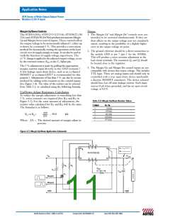
Typical Application
The basic implementation of Auto-Track™ allows for
simultaneous voltage sequencing of a number of Auto-
Track™ compliant modules. Connecting the Track control
pins of two or more modules forces the Track control of
all modules to follow the same collective RC ramp wave-
form, and allows them to be controlled through a single
transistor or switch; Q1 in Figure 3-4.
2. The Auto-Track™ function will track almost any
voltage ramp during power up, and is compatible
with ramp speeds of up to 5 V/ms.
3. The absolute maximum voltage that may be applied to the
Track pin is Vin.
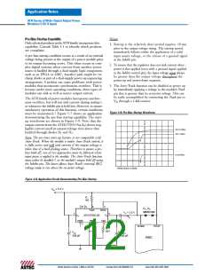
To initiate a power-up sequence, it is recommended that
the Track control be first pulled to ground potential.
This should be done at or before input power is applied
to the modules, and then held for at least 10 ms thereaf-
ter. This brief period gives the modules time to complete
their internal soft-start initialization. Applying a logic-
level high signal to the circuit’s On/Off Control turns
Q1 on and applies a ground signal to the Track pins. After
completing their internal soft-start intialization, the out-
put of all modules will remain at zero volts while Q1 is on.
4. The module will not follow a voltage at its Track control
input until it has completed its soft-start initialization.
This takes about 10 ms from the time that the module
has sensed that a valid voltage has been applied its input.
During this period, it is recommended that the Track
pin be held at ground potential.
5. Once its soft-start initialization is complete, the module
is capable of both sinking and sourcing current when
following the voltage at the Track pin.
6. The Auto-Track™ function can be disabled by
connecting the Track pin to the input voltage (Vin)
through a 1-kΩ resistor. When Auto-Track™ is
disabled, the output voltage will rise faster
10 ms after a valid input voltage has been applied to the
modules, Q1 may be turned off. This allows the track con-
trol voltage to automatically rise toward to the modules'
input voltage. During this period the output voltage of
following the application of input power.
**Auto-Track is a trademark of Texas Instruments, Inc.
North America (USA): 1-888-41-ASTEC
Europe (UK): 44(1384)842-211
Asia (HK): 852-2437-9662

 ASTEC [ Astec America, Inc ]