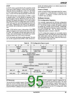
The PCI configuration utility must also set the IOEN bit
in the PCI Command register to enable I/O accesses to
the Am79C978 controller. For memory mapped I/O ac-
cess, the PCI Memory Mapped I/O Base Address reg-
ister controls the start address of the memory space.
The MEMEN bit in the PCI Command register must also
be set to enable the mode. Both base address registers
can be active at the same time.
tialization block in order for the receiver to accept
unicast frames directed to this station.
The six bytes of the IEEE station address occupy the
first six locations of the Address PROM space. The
next six bytes are reserved. Bytes 12 and 13 should
match the value of the checksum of bytes 1 through 11
and 14 and 15. Bytes 14 and 15 should each be ASCII
“W” (57h). The above requirements must be met in
order to be compatible with AMD driver software.
APROMWE bit (BCR2, bit 8) must be set to 1 to enable
write access to the Address PROM space.
The Am79C978 controller supports two modes for ac-
cessing the I/O resources. For backwards compatibility
with AMD’s 16-bit Ethernet controllers, Word I/O is the
default mode after power up. The device can be config-
ured to DWord I/O mode by software.
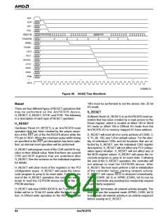
Reset Register
A read of the Reset register creates an internal soft-
ware reset (S_RESET) pulse in the Am79C978 control-
ler. The internal S_RESET pulse that is generated by
this access is different from both the assertion of the
hardware RST pin (H_RESET) and from the assertion
of the software STOP bit. Specifically, S_RESET is the
equivalent of the assertion of the RST pin (H_RESET)
except that S_RESET has no effect on the BCR or PCI
Configuration space locations.
I/O Registers
The Am79C978 controller registers are divided into two
groups. The Control and Status Registers (CSR) are
used to configure the Ethernet MAC engine and to ob-
tain status information. The Bus Control Registers
(BCR) are used to configure the bus interface unit and
the LEDs. Both sets of registers are accessed using in-
direct addressing.
The CSR and BCR share a common Register Address
Port (RAP). There are, however, separate data ports.
The Register Data Port (RDP) is used to access a
CSR. The BCR Data Port (BDP) is used to access a
BCR.
The NE2100 LANCE-based family of Ethernet cards
requires that a write access to the Reset register fol-
lows each read access to the Reset register. The
Am79C978 controller does not have a similar require-
ment. The write access is not required and does not
have any effect.
In order to access a particular CSR location, the RAP
should first be written with the appropriate CSR ad-
dress. The RDP will then point to the selected CSR. A
read of the RDP will yield the selected CSR data. A
write to the RDP will write to the selected CSR. In order
to access a particular BCR location, the RAP should
first be written with the appropriate BCR address. The
BDP will then point to the selected BCR. A read of the
BDP will yield the selected BCR data. A write to the
BDP will write to the selected BCR.
Note: The Am79C978 controller cannot service any
slave accesses for a very short time after a read access
of the Reset register, because the internal S_RESET
operation takes about 1 ms to finish. The Am79C978
controller will terminate all slave accesses with the as-
sertion of DEVSEL and STOP while TRDY is not as-
serted, signaling to the initiator to disconnect and retry
the access at a later time.
Word I/O Mode
Once the RAP has been written with a value, the RAP
value remains unchanged until another RAP write oc-
curs, or until an H_RESET or S_RESET occurs. RAP
is cleared to all 0s when an H_RESET or S_RESET oc-
curs. RAP is unaffected by setting the STOP bit.
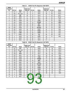
After H_RESET, the Am79C978 controller is pro-
grammed to operate in Word I/O mode. DWIO (BCR18,
bit 7) will be cleared to 0. Table 25 shows how the 32
bytes of address space are used in Word I/O mode.
All I/O resources must be accessed in word quantities
and on word addresses. The Address PROM locations
can also be read in byte quantities. The only allowed
DWord operation is a write access to the RDP, which
switches the device to DWord I/O mode. A read access
other than listed in the table below will yield undefined
data; a write operation may cause unexpected repro-
gramming of the Am79C978 control registers. Table 26
shows legal I/O accesses in Word I/O mode.
Address PROM Space
The Am79C978 controller allows for connection of a
serial EEPROM. The first 16 bytes of the EEPROM will
be automatically loaded into the Address PROM
(APROM) space after H_RESET. Additionally, the first
six bytes of the EEPROM will be loaded into CSR12 to
CSR14. The Address PROM space is a convenient
place to store the value of the 48-bit IEEE station ad-
dress. It can be overwritten by the host computer, and
its content has no effect on the operation of the
Am79C978 controller. The software must copy the sta-
tion address from the Address PROM space to the ini-
96
Am79C978

 AMD [ AMD ]