minate all network activity in an orderly sequence be-
fore setting the STOP bit.
STOP
A STOP reset is generated by the assertion of the
STOP bit in CSR0. Writing a 1 to the STOP bit of CSR0,
when the stop bit currently has a value of 0, will initiate
a STOP reset. If the STOP bit is already a 1, then writ-
ing a 1 to the STOP bit will not generate a STOP reset.
Power on Reset
Power on Reset (POR) is generated when the control-
ler is powered up. POR generates a hardware reset
(H_RESET). In addition, it clears some bits that
H_RESET does not affect.
STOP will reset all or some portions of CSR0, 3, and 4
to default values. For the identity of individual CSRs
and bit locations that are affected by STOP, see the in-
dividual CSR register descriptions. STOP will not affect
any of the BCR and PCI configuration space locations.
STOP will cause the microcode program to jump to its
reset state. Following the end of the STOP operation,
the controller will not attempt to read the EEPROM de-
vice.
Software Access
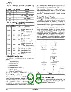
PCI Configuration Registers
The controller implements the 256-byte configuration
space as defined by the PCI draft specification revision
2.2. The 64-byte header includes all registers required
to identify the controller and its function. Additionally,
PCI Power Management Interface registers are imple-
mented at location 40h - 47h. The layout of the PCI
configuration space is shown in Table 24.
Note: STOP will not cause a deassertion of the REQ
signal, if it happens to be active at the time of the write
to CSR0. The controller will wait until it gains bus own-
ership, and it will first finish all scheduled bus master
accesses before the STOP reset is executed.
The PCI configuration registers are accessible only by
configuration cycles. All multi-byte numeric fields follow
little endian byte ordering. All write accesses to Re-
served locations have no effect; reads from these loca-
tions will return a data value of 0.
STOP terminates all network activity abruptly. The host
can use the suspend mode (SPND, CSR5, bit 0) to ter-
Table 24. PCI Configuration Space Layout
16 15
31
24
23
Device ID
8
7
0
Offset
00h
04h
08h
0Ch
10h
14h
18h
1Ch
20h
24h
28h
2Ch
30h
34h
38h
3Ch
40h
44H
.
Vendor ID
Command
Status
Base-Class
Reserved
Sub-Class
Programming IF
Latency Timer
Revision ID
Reserved
Header Type
I/O Base Address
Memory Mapped I/O Base Address
Reserved
Reserved
Reserved
Reserved
Reserved
Subsystem ID
Subsystem Vendor ID
Expansion ROM Base Address
Reserved
CAP-PTR
Reserved
MAX_LAT
MIN_GNT
PMCSR_BSE
Interrupt Pin
Interrupt Line
CAP_ID
PMC
NXT_ITM_PTR
DATA_REG
PMCSR
Reserved
Reserved
.
FCh
I/O Resources
The Am79C978 controller supports mapping the ad-
dress space to both I/O and memory space. The value
in the PCI I/O Base Address register determines the
start address of the I/O address space. The register is
typically programmed by the PCI configuration utility
after system power-up.
The Am79C978 controller requires 32 bytes of address
space for access to all the various internal registers as
well as to some setup information stored in an external
serial EEPROM. A software reset port is available, too.
Am79C978
95

 AMD [ AMD ]