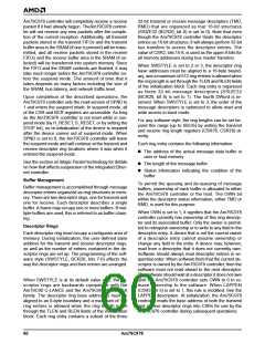
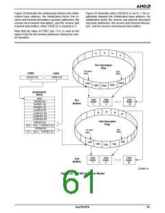
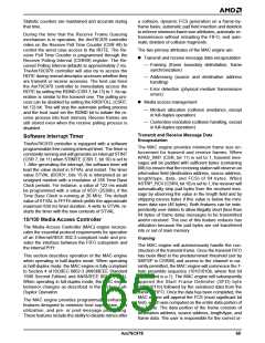
Figure 33 illustrates the relationship between the initial-
ization base address, the initialization block, the re-
ceive and transmit descriptor ring base addresses, the
receive and transmit descriptors, and the receive and
transmit data buffers, when SSIZE32 is cleared to 0.
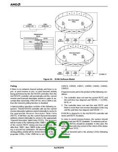
Figure 34 illustrates when SSIZE32 is set to 1, the re-
lationship between the initialization base address, the
initialization block, the receive and transmit descriptor
ring base addresses, the receive and transmit descrip-
tors, and the receive and transmit data buffers.
Note that the value of CSR2, bits 15-8, is used as the
upper 8-bits for all memory addresses during bus mas-
ter transfers.
N
N
N
N
•
•
•
Rcv Descriptor
Ring
1st desc.
start
2nd
desc.
CSR2
CSR1
IADR[31:16]
IADR[15:0]
RMD0
RMD
RMD
RMD
RMD
Initialization
Block
MOD
PADR[15:0]
Data
Data
Data
Rcv
Buffers
Buffer
1
Buffer
2
Buffer
N
PADR[31:16]
PADR[47:32]
LADRF[15:0]
LADRF[31:16]
LADRF[47:32]
LADRF[63:48]
RDRA[15:0]
M
M
M
M
•
•
•
Xmt Descriptor
Ring
RLE
TLE
RDRA[23:16]
TDRA[15:0]
TDRA[23:16]
RES
2nd
desc.
1st desc.
start
RES
TMD
TMD
TMD
TMD
TMD
Data
Buffer
M
Data
Buffer
1
Data
Buffer
2
Xmt
Buffers
22206B-36
Figure 33. 16-Bit Software Model
Am79C978
61

 AMD [ AMD ]