Am79C978 controller will completely receive a receive
packet if it had already begun. TheAm79C978 control-
ler will not receive any new packets after the comple-
tion of the current reception. Additionally, all transmit
packets stored in the transmit FIFOs and the transmit
buffer area in the SRAM (if one is present) will be trans-
mitted, and all receive packets stored in the receive
FIFOs and the receive buffer area in the SRAM (if se-
lected) will be transferred into system memory. Since
the FIFO and the SRAM contents are flushed, it may
take much longer before the Am79C978 controller en-
ters the suspend mode. The amount of time that it
takes depends on many factors including the size of
the SRAM, bus latency, and network traffic level.
32-bit transmit or receive message descriptors (TMD,
RMD) that are organized as four 16-bit structures
(SSIZE32 (BCR20, bit 8) is set to 0). Note that even
though the Am79C978 controller treats the descriptor
entries as 16-bit structures, it will always perform 32-bit
bus transfers to access the descriptor entries. The
value of CSR2, bits 15-8, is used as the upper 8-bits for
all memory addresses during bus master transfers.
When SWSTYLE is set to 2 or 3, the descriptor ring
base addresses must be aligned to a 16-byte bound-
ary, and a maximum of 512 ring entries is allowed when
the ring length is set through the TLEN and RLEN fields
of the initialization block. Each ring entry is organized
as three 32-bit message descriptors (SSIZE32
(BCR20, bit 8) is set to 1). The fourth DWord is re-
served. When SWSTYLE is set to 3, the order of the
message descriptors is optimized to allow read and
write access in burst mode.
Upon completion of the described operations, the
Am79C978 controller sets the read-version of SPND to
1 and enters the suspend mode. In suspend mode, all
of the CSR and BCR registers are accessible. As long
as the Am79C978 controller is not reset while in sus-
pend mode (by H_RESET, S_RESET, or by setting the
STOP bit), no re-initialization of the device is required
after the device comes out of suspend mode. When
SPND is set to 0, the Am79C978 controller will leave
the suspend mode and will continue at the transmit and
receive descriptor ring locations where it was when it
entered the suspend mode.
For any software style, the ring lengths can be set be-
yond this range (up to 65535) by writing the transmit
and receive ring length registers (CSR76, CSR78) di-
rectly.
Each ring entry contains the following information:
n The address of the actual message data buffer in
user or host memory
See the section on Magic Packet technology for details
on how that affects suspension of the integrated Ether-
net controller.
n The length of the message buffer
n Status information indicating the condition of the
buffer
Buffer Management
To permit the queuing and de-queuing of message
buffers, ownership of each buffer is allocated to either
the Am79C978 controller or the host. The OWN bit
within the descriptor status information, either TMD or
RMD, is used for this purpose.
Buffer management is accomplished through message
descriptor entries organized as ring structures in mem-
ory. There are two descriptor rings, one for transmit and
one for receive. Each descriptor describes a single
buffer. A frame may occupy one or more buffers. If mul-
tiple buffers are used, this is referred to as buffer chain-
ing.
When OWN is set to 1, it signifies that the Am79C978
controller currently has ownership of this ring descrip-
tor and its associated buffer. Only the owner is permit-
ted to relinquish ownership or to write to any field in the
descriptor entry. A device that is not the current owner
of a descriptor entry cannot assume ownership or
change any field in the entry. A device may, however,
read from a descriptor that it does not currently own.
Software should always read descriptor entries in se-
quential order. When software finds that the current de-
scriptor is owned by the Am79C978 controller, then the
software must not read ahead to the next descriptor.
The software should wait at a descriptor it does not own
until the Am79C978 controller sets OWN to 0 to re-
lease ownership to the software. When LAPPEN
(CSR3, bit 5) is set to 1, this rule is modified. See the
LAPPEN description. At initialization, the Am79C978
controller reads the base address of both the transmit
and receive descriptor rings into CSRs for use by the
Am79C978 controller during subsequent operations.
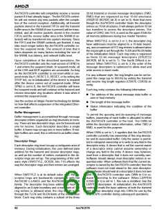
Descriptor Rings
Each descriptor ring must occupy a contiguous area of
memory. During initialization, the user-defined base
address for the transmit and receive descriptor rings,
as well as the number of entries contained in the de-
scriptor rings are set up. The programming of the soft-
ware style (SWSTYLE, BCR20, bits 7-0) affects the
way the descriptor rings and their entries are arranged.
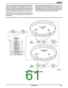
When SWSTYLE is at its default value of 0, the de-
scriptor rings are backwards compatible with the
Am79C90 C-LANCE and the Am79C96x PCnet-ISA
family. The descriptor ring base addresses must be
aligned to an 8-byte boundary and a maximum of 128
ring entries is allowed when the ring length is set
through the TLEN and RLEN fields of the initialization
block. Each ring entry contains a subset of the three
60
Am79C978

 AMD [ AMD ]