to CSR15, and then setting the START bit in CSR0.
Note that this form of restart will not perform the same
in the Am79C978 controller as in the C-LANCE device.
In particular, upon restart, the Am79C978 controller re-
loads the transmit and receive descriptor pointers with
their respective base addresses. This means that the
software must clear the descriptor OWN bits and reset
its descriptor ring pointers before restarting the
Am79C978 controller. The reload of descriptor base
addresses is performed in the C-LANCE device only
after initialization, so that a restart of the C-LANCE
without initialization leaves the C-LANCE pointing at
the same descriptor locations as before the restart.
Buffer Management Unit
The Buffer Management Unit (BMU) is a microcoded
state machine which implements the initialization pro-
cedure and manages the descriptors and buffers. The
buffer management unit operates at half the speed of
the CLK input.
Initialization
Initialization includes the reading of the initialization
block in memory to obtain the operating parameters.
The initialization block can be organized in two ways.
When SSIZE32 (BCR20, bit 8) is at its default value of
0, all initialization block entries are logically 16-bits
wide to be backwards compatible with the Am79C90
C-LANCE and Am79C96x PCnet-ISA family. When
SSIZE32 (BCR20, bit 8) is set to 1, all initialization
block entries are logically 32-bits wide. Note that the
Am79C978 controller always performs 32-bit bus
transfers to read the initialization block entries. The ini-
tialization block is read when the INIT bit in CSR0 is
set. The INIT bit should be set before or concurrent with
the STRT bit to insure correct operation. Once the ini-
tialization block has been completely read in and inter-
nal registers have been updated, IDON will be set in
CSR0, generating an interrupt (if IENA is set).
Suspend
The Am79C978 controller offers two suspend modes
that allow easy updating of the CSR registers without
going through a full re-initialization of the device. The
suspend modes also allow stopping the device with or-
derly termination of all network activity.
The host requests the Am79C978 controller to enter
the suspend mode by setting SPND (CSR5, bit 0) to 1.
The host must poll SPND until it reads back 1 to deter-
mine that the Am79C978 controller has entered the
suspend mode. When the host sets SPND to 1, the pro-
cedure taken by the Am79C978 controller to enter the
suspend mode depends on the setting of the fast sus-
pend enable bit (FASTSPND, CSR7, bit 15).
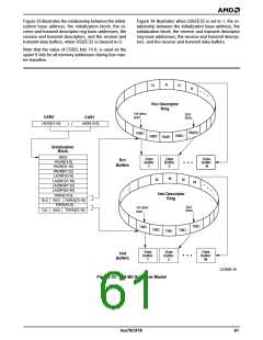
The Am79C978 controller obtains the start address of
the initialization block from the contents of CSR1 (least
significant 16 bits of address) and CSR2 (most signifi-
cant 16 bits of address). The host must write CSR1 and
CSR2 before setting the INIT bit. The initialization block
contains the user defined conditions for operation, to-
gether with the base addresses and length information
of the transmit and receive descriptor rings.
When a fast suspend is requested (FASTSPND is set
to 1), the Am79C978 controller performs a quick entry
into the suspend mode. At the time the SPND bit is set,
the Am79C978 controller will continue the DMA pro-
cess of any transmit and/or receive packets that have
already begun DMA activity until the network activity
has been completed. In addition, any transmit packet
that had started transmission will be fully transmitted
and any receive packet that had begun reception will
be fully received. However, no additional packets will
be transmitted or received and no additional transmit or
receive DMA activity will begin after network activity
has ceased. Hence, the Am79C978 controller may
enter the suspend mode with transmit and/or receive
packets still in the FIFOs or the SRAM. This offers a
worst case suspend time of a maximum length packet
over the possibility of completely emptying the SRAM.
Care must be exercised in this mode, because the en-
tire memory subsystem of the Am79C978 controller is
suspended. Any changes to either the descriptor rings
or the SRAM can cause the Am79C978 controller to
start up in an unknown condition and could cause data
corruption.
There is an alternate method to initialize the
Am79C978 controller. Instead of initialization via the
initialization block in memory, data can be written di-
rectly into the appropriate registers. Either method or a
combination of the two may be used at the discretion of
the programmer. Please refer to Appendix A, Alterna-
tive Method for Initialization for details on this alternate
method.
Re-Initialization
The transmitter and receiver sections of the
Am79C978 controller can be turned on via the initial-
ization block (DTX, DRX, CSR15, bits 1-0). The states
of the transmitter and receiver are monitored by the
host through CSR0 (RXON, TXON bits). The
Am79C978 controller should be re-initialized if the
transmitter and/or the receiver were not turned on dur-
ing the original initialization and it was subsequently re-
quired to activate them, or if either section was shut off
due to the detection of an error condition (MERR,
UFLO, TX BUFF error).
When FASTSPNDE is 0 and the SPND bit is set, the
Am79C978 controller may take longer before entering
the suspend mode. At the time the SPND bit is set, the
Am79C978 controller will complete the DMA process of
a transmit packet if it had already begun, and the
Re-initialization may be done via the initialization block
or by setting the STOP bit in CSR0, followed by writing
Am79C978
59

 AMD [ AMD ]