AMD
P R E L I M I N A R Y
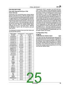
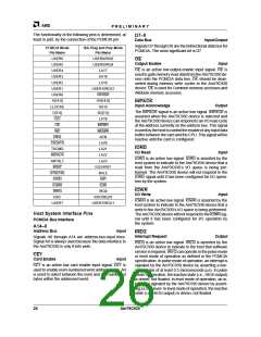
The functionality of the following pins is determined, at
least in part, by the connection of the PCMCIA pin:
D7–0
Data Bus
Input/Output
Signals D7 through D0 are the bidirectional data bus for
PCMCIA. The most significant bit is D7.
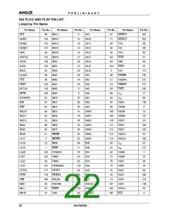
PCMCIA Mode
Pin Name
ISA Plug and Play Mode
Pin Name
USER6
USER5
USER4
USER3
USER2
USER1
USER0
A[14:0]
LLOCKE
D[7:0]
USER6/IRQ5
USER5/IRQ4
LA17
OE
Output Enable
Input
OE is an active low-output-enable input signal. OE is
used to gate memory read data from the Am79C930 de-
vice onto the PCMCIA data bus. OE should be deas-
serted during memory write cycles to the Am79C930
device. OE is used for Common memory accesses and
Attribute memory accesses.
SA16
LA19
USER1/IRQ12
RFRSH
SA[14:0]
SA15
INPACK
Input Acknowledge
Output
The INPACK signal is an active low signal. INPACK is
asserted when the Am79C930 device is selected and
the Am79C930 device can respond to an I/O read cycle
at the address currently on the address bus. This signal
is used by the host to control the enable of any input data
buffer between the card and the CPU. This signal will be
inactive until the card is configured.
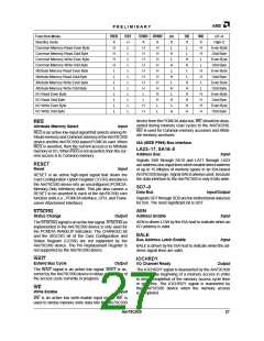
SD[7:0]
LA18
CE1
OE
MEMR
MEMW
AEN
WE
REG
TXDATA
TXCMD
INPACK
ANTSLT
WAIT
LA20
IORD
I/O Read
LA21
Input
LA22
IORD is an active low signal. IORD is asserted by the
host system to indicate to the Am79C930 device that a
read from the Am79C930’s I/O space is being per-
formed. The Am79C930 device will not respond to the
IORD signal until it has been configured for I/O opera-
tion by the system.
LA23
IOCHRDY
BALE
STSCHG
IORD
IOR
IOWR
IOW
IOWR
IREQ
IRQ9
I/O Write
Input
RXC
RXC/IRQ10
USER7/IRQ11
IOWR is an active low signal. IOWR is asserted by the
host system to indicate to the Am79C930 device that a
write to the Am79C930’s I/O space is being performed.
TheAm79C930devicewillnotrespondtotheIOWR sig-
nal until it has been configured for I/O operation by
the system.
USER7
Host System Interface Pins
PCMCIA Bus Interface
A14–0
Address Bus
Input
IREQ
Interrupt Request
Output
Signals A0 through A14 are address-bus-input lines.
Signal A0 is always used because the data interface to
the Am79C930 is only 8-bits wide.
IREQ is an active low signal. IREQ is asserted by the
Am79C930 device to indicate to the host that software
service is required. IREQ can operate in the pulse mode
or level mode of operation as defined in the PCMCIA
specification. In pulse mode of operation, an interrupt is
signaled by the Am79C930 device by asserting a low-
going pulse of at least 0.5 microseconds (µs). In pulse
mode of operation, the inactive state (i.e., HIGH output)
is driven, not floated. In level mode of operation, an in-
terrupt is signaled by the Am79C930 device by assert-
ing a LOW level. In level mode of operation, the inactive
state (i.e., HIGH output) is driven, not floated.
CE1
Card Enable
Input
CE1 is an active low card enable input signal. CE1 is
used to enable even-numbered word address bytes. A0
is used to select between the even and odd numbered
bytes within the addressed word.
26
Am79C930

 AMD [ AMD ]